
Bcook
Members
-
Joined
-
Last visited
Everything posted by Bcook
-
You got me All I was thinking about was the fact that it would be unusual to wire the primary winding in series on the phase line
-
Sorry, I must be missing something
-
I am wondering what changes you see? I see a capacitor in series, not parallel. And a coil winding wired in series with a load, that is it for the primary line. The AC source is normal and the motor is normal. What is the third? But, what I was referring to as changing the operating principle is the primary winding.
-
Thanks for your input. I usually make it known that I have no formal education in electrical engineering or electromagnetism. I can explain everything going on in this circuit, while never talking about anything electrical, I know that sounds odd. I explained what you WILL see if you do not have resistance present on the secondary coil winding. Current is whatever the load requires based on voltage, voltage change anywhere in the circuit is controllable at will, up or down, to a point. This add-on component is about field interactions, I am trying to keep it simple by only talking about current from coil to coil. Whatever current is on the primary is what current is on the secondary, under ideal conditions it never varies. I have found that any theorizing of data in this circuit layout based on the current paradigm will be incorrect, again I know that sounds odd or even unbelievable, but true. I'm hoping for a starting point, math This circuit is about non linear magnetic moments, field lines. Field control. The very basic thing about this, a field line causes a field line, that was discovered 200 years ago. I have found that an aspect of that discovery has been overlooked, I put my finger on it about 10 years ago. And I'm still trying to get is recognized. Thank you, I'm not trying to be negative as to what anyone says. If computer simulations can't predict it, it's never been seen or experienced. I'm not sure what you see. But I would like to know. Thanks
-
Theorizing whats going on in this circuit will be incorrect. Actual test data is what tells the real story. If I tried to explain whats going on and I have, I would be told I'm wrong and I don't understand, It's been third party tested many times, it's very predictable and proven, even if most don't believe, the testers do believe, they just don't understand the math. In this case, changing the operating principles of one component, changes everything. This circuit is about field control. Non linear directional fields It's nice to see it being looked at though.
-
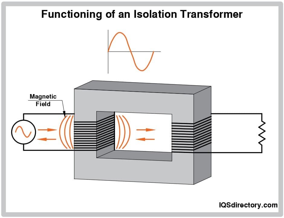
The fundamental operating principle for all standard isolation transformers remains electromagnetic induction (Faraday's Law). There are no widely used "alternative operating principles" for isolation transformers. This setup is not used for transferring AC power. But, by changing principles of operation, the math changes based on the data. This is the normal setup for an Isolation transformer. But, when you make one change to the core setup, like this. All the mathematical data changes. I can’t find any math for these changes. So I’m looking for someone who may be willing to help, a Mathematician. To keep things simple for now, think of an ideal model, no resistance on the secondary winding. And a 1 to 1 turns ratio. Current on the primary winding is dictated by a primary load. Voltage on the primary will be the same as what the source supplies and current will be the same as what the load dedicates. Current on the secondary winding will be exactly the same as the primary winding. With a closed circuit and ideally no resistance on the secondary winding, there will be no voltage on the secondary winding. At this point, it's as if the secondary is not even there, meaning the primary does not see any change to voltage or current, no sine wave distortion, nothing changes. The major changes come when resistance is experienced on the secondary winding. This circuit layout has been third party tested many times. And I would be more than happy to share test data. If any Mathematicians on here are interested, that would be great. I keep being told after testing, we don't understand the math. The data is very predictable, but I’m not into mathematical equations. That's why I’m looking for help. And just in case, this is not theoretical, it’s a fully functional circuit. If this is inappropriate on this site, I apologize.
-
I would like to say something about this circuit. I understand when I talk about this it seems to offend some people, and that is just the opposite of what I am trying to achieve. This circuit is not unusual but it is also not usual, because it came to be in the very early 1900s. The transformer style component within the circuit would have been called a magnetic amplifier. The secondary winding of the magnetic amplifier was supplied with an external current to be used to alter the magnetic fields within the iron core to limit current on the primary line. I discovered that I can create the same scenario of controlling the magnetic fields within the iron core without adding a secondary current, achieving the same desired effect but with an added benefit. That is simply what I am trying to point out, the process can be achieved with an alternate method that can ultimately increase efficiency if used correctly. I’m sorry if I have created any confusion. It’s difficult to try to explain something when there are people who really don’t want to hear it.
-
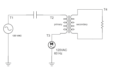
the primary winding is in series with a primary load, only to be able to use the magnetic field the secondary winding is connected across it's two leads, starting with a connection having zero resistance, ultimately adding resistance for a desired effect on the primary winding, one lead of the secondary can be grounded if desired, then adding resistance to the other lead that also has to attach to a ground. I would like to stick with this circuit for now, the other circuit with the two motors, it's about field lines only, use with minimal negative effect. I hope the diagram helps

-
You are absolutely correct, I apologize. So if I may, let me address what you are talking about. To stick with the actual data, there is only one way to connect to the coil leads, simply because the secondary is shorted, with or without resistance. You can even flip the coil over, now the windings are backwards vs the primary, and nothing changes. I am mechanical by nature meaning everything to me has a mechanical aspect. My only understanding is that when a magnetic field interacts with a dia material the material induces a magnetic field of its own with oppositional fields. The mechanical aspect of that for me is when I described two cogged gears working together. In this equation I'm assuming this would be if the secondary coil is shorted having no resistance across the leads? How would the equation change based on resistance changes across the leads of the secondary? Any resistance across the secondary leads causes changes on the primary line. When adding resistance the secondary coil follows ohms law starting with current adding resistance and equating to voltage. I don't know what was removed from the post or why? If you remember which one I will repost it.
-
If it seems that way I sincerely apologize. In this statement, I did not talk about the fan when mentioning the air gap within the iron core, that was your perception of what I was saying. I mentioned the air gap because the fields within the iron core will not be fully utilized. My perspective is so vastly different it does not coincide with the current paradigm. The foundation of my perception is diamagnetism, when a magnetic field interacts with a diamagnetic material that material generates a magnetic field. When I look at what you posted for me, it doesn't make sense to me based on what I see happening, like what I am showing doesn't seem make sense to you. I try to bridge the gap by trying to explain the way I see it. It's a field line, think of it as two cogged gears, whatever direction one moves the other is opposite. Its simply two field lines regardless of the layout. When a magnetic field interacts with an inductor winding, its interacting with a strand of wire, it doesn't matter if it's a single strand or overlaid 100 times. In other words it doesn't matter the number of windings as far as the field line goes, increasing the number of windings only increases the intensity experienced on the strand of wire. My focus is not just about the field, its about the field line, and that seems to confuse people. During a magnetic interaction with a diamagnetic there is only one field line, while that field line is present there are two phenomenon, interact with that one field line and see how the two phenomenon change, this is what this circuit is about. That's the reason I mention that this circuit is not about the motor it's not about the fields within the motor it's about the field line occupying the wire that connect the motor to the source, and the source is just a magnetic interaction. When I first developed this circuit I had someone do testing, he teaches mathematics, and is a licensed electrical engineer because when school is out he does testing for NASA and Los Alamos. He validated the data but could not understand the magnetics, he said I kind of get it, but I don't really get it. And said there are no mathematical equations for what he tested. The data was real but he couldn't understand why. If you look at a lab scope connected to a strand of wire, you will see a voltage and current waveform pointing in the same direction, north or south. The north or south direction of the waveform is just indicating the direction of the field line. I get told all the time, that is not how it works, and yet no one can explain what's going on in these circuits. I probably have made the situation worst but I can only explain it the way I see it. Thanks
-
I have been showing and demoing my circuits for years, in every case the data within the circuit is validated. The most recent testing for me was in the first of 2023 at Florida Polytechnic, which I paid good money to have done. And yet here I am trying to find someone in the science world who is willing to look at it objectively. Apparently the science world cannot look at this objectively. My holdup, business people that I talk with get excited about the prospect of what I'm telling them, then their next step is talk to their electrical engineers, and you know whats said then, that shit can't be done. I would imagine that if a research group from MIT was presenting what I am, it would be all the rage. And yes, I have reached out to MIT multiple times as well as many other universities all over the US, only to get no response. So, my exact question, WHY? Why will no one look at this objectively? even though it's been proven
-
I have done another more detailed demo for whoever may want to see the harvester circuit. My focus is on the add-on component, while making sure the original circuit is not compromised. The motor used is just to provide a magnetic field intensity as well as a time variation of that magnetic field. Most seem to believe its about the motor and it's fields, its not, the line connecting the source to the motor has the same magnetic intensity as the motor. According to diamagnetism a magnetic field induces a magnetic field, the foundation of this circuit. Detailed Demo The source is a magnetic interaction, the harvester unit is a magnetic interaction and the motor is a magnetic interaction. I hope this helps
-
I can see where things can get confusing, what demo would you like more detail on? I would be more than happy to do one as slow and in as much detail as I can. Were they the ones in the box? If so only one is hooked up and being used.
-
Sure Patent # US 11,309,735 B1
-
Just because it has two coils and an iron core doesn't mean it is using the operating principles of a transformer. Yes, if you are asking because of the demo showing a small motor, that is a 12 volt dc motor found in any car. I am confused about this statement, this is the diagram I developed some five years ago and was issued a patent on. Which is not just about its components, it's about it's operating principles and what it does. This circuit is so simple, all that can change is placing the capacitor or coils in different locations within the circuit, which I have done, and tested for changes. The motor used for load just makes available a predetermined magnetic intensity of about 2.1 amps and a loaded speed of about 1400 rpm. With a power factor of .6 without the coil setup in the circuit, with the coil setup it's .65 power factor. The capacitor used in the demo, 220 v.ac 54 MFD here is data on transformer housing isolation transformer - ds_st_m4l_series-1633501.pdf This circuit is about accessing the available magnetic intensity and using it as a starting point for other purposes. In it's controlled state, all that matters is whats going on within the iron core while not having any effect on motor performance or current draw. The motor itself provides two things, the magnetic intensity as well as a time variation of that magnetic intensity. Every since I developed this circuit I have been trying to explain in detail this circuit, it seems that my perspective does not coincide with what science says. That appears to be what happened on the last forum, he was trying to understand the coil setup based on electrical engineering beliefs. When he could not understand and his simulations could not understand, he quit? All while never denying the data, no one as ever denied the data. They just seem to believe it is not possible. Two different videos, different motors, I actually use three different motors for different demos. I'm not sure what you saw? or associated. The two demos are a motor with a .6 power factor and the other is a motor with a .3 power factor, different motors, different specs. Showing how power factor difference affects the circuit, lower power factor means the secondary potential is much higher with the correct capacitance values on the primary side. Secondary potential is based on power factor of the primary line and the resistance across the secondary leads. One of the points that I can't seem to get across to anyone is the "transformer", it's just two coils housed within a common core, it's sole purpose, field line interactions. One of the things that I can't understand is if you take this circuit, analyze all the interactions independently, damn near everyone on an individual basis is condoned by your science and yet when you put them together in a neat little package to work in unity, it's a completely different story. With that being said, I have been trying to find someone (professional) who's willing to look at certain aspects from a different perspective, field line only. Thanks, I hope I haven't deterred you.
-
Thank you In the picture you are showing, that is a transformer setup, most tend to see that when looking at what I am doing. I in no way use the coil setup as a transformer, it is very specific for field line interactions. If you are interested in investigating, which is why I am on here, I will provide whatever you need for you to analyze. If you are really interested, here is a link to months of corresponding with someone else on another forum, until he quite. Forum discussion Loaded with data and many demos, as well as me explaining my mindset. Just remember, no formal schooling means my terminology can be a little difficult, I say it the way I see it. I hope you are interested, thanks
-
Sorry, everyone seems to talk like they understand what is going on, it was just a statement You are arguing with science, I just did copy / paste I just wonder where you heard me talking about a transformer that I am dealing with? I did mention transformer by comparison. If I analyze your statement, it sounds like you are saying AC does not have a circular magnetic field? Above I said "envision as slow motion" meaning one field line at a time regardless of direction. The jumping button magnetic is indeed because of AC, please explain why the changing fields no longer interact with the surrounding iron. It is my website, as far as how professional it looks, I can only do what I have resources for. What parts of or is it all parts that you don't see anything unexpected? If you expect to see the data that I show, then I guess you have more understanding then any computer simulation. Maybe you would have better luck simulating that circuit, if so I would love to see the data. As far as the explanations being hazy, if you can't envision what the field lines are doing when the circuit is active, while disregarding voltage and current, I can understand why it would be hazy. Here is another demo that is focused just on field lines, voltage in this setup is completely disregarded. Field line demo Thanks for the replies
-
Ok, Everyone has an opinion and yet no one has an answer, that's fine. If you spent all the time you felt you needed to conduct testing, as you would prefer, to whatever extent, you still may not understand. This is not being negative to anyone, let me say that again and no disrespect for anyone's views or opinions. I was not going to say anything but, On another forum I spent about 5 months corresponding with someone as he tried to understand what I am doing. When he could not computer simulate circuits or understand the way I see things, he did like everyone else I have ever spent time with, quite. The reason you can't see it, is you don't look at what I look at, My circuits are very simple by design, meaning very little to follow as far as field lines. Magnetic field lines are imaginary lines that represent the direction and strength of magnetic force at any given point in space An electromagnetic field is a magnetic field, if it's a magnetic field it can be viewed as field lines for reference. For me it starts at the source, DIAMAGNETISM first observed 1778 Here is a diagram of the harvester circuit, ignore voltage and current, just envision field line direction in slow motion. I know I left voltage references. By controlling the resistance of the secondary winding, I can control every field line intensity in the circuit. With the capacitor, there are 3 main field lines. The closest thing to this is a magnetic amplifier, as early as 1885 How does a magnetic field line act and react to it's surroundings? I keep trying to get one point across, electromagnetism is, magnetic field line ---current---voltage, two phenomenon with one field line. The secondary winding in this circuit, with no resistance, has the exact magnetic field and current as the primary winding, voltage only becomes present within the winding when resistance is present across it's leads. It's all about field line interactions.

-
Thanks for the replies. If anyone is interested in seeing some demo's here is a web address showing and explaining what I see and do. www.globalenergyapplications.com I am not trying to hide anything, I am trying to explain the way I see the fields. In my years of research and testing there have been dozens of professors baffled about the data they see in my circuits. And never once has a professor been able to say "it's not real" or "you don't see what you think you see" because with hands on testing they see exactly what I see as far as the data goes.
-
I am new to this forum, and interested in talking about very specific electromagnetic field line interactions. When I reference field lines I am talking the field lines around a conductor, in other words the same field lines you would use to reference linear direction of current. I have no formal education in the field so my terminology leaves a lot to be desired. I do have about 12 years of research on just field lines and their interactions. I have several patents that are focused on field line interactions only. When I talk about what I do, people seem to get lost and when I show whats going on it gets even worse. Electromagnetism is a combination of electricity and magnetism, the magnetic field is perceived as being a north field or a south field. For reference, my latest patent is for power factor correction harvesting. The short of it is, if the volt amps for the motor to perform it's task is 1000 volt amps and it has a .65 power factor then when corrected to a 1 power factor then the .35 difference is harvested onto a separate circuit for independent use, and motor performance is completely unaffected, as is current draw. So I am just looking for someone who can follow and understand field lines, and my circuits can not be computer simulated, yet. If this is unwelcome on this forum I apologize, Thanks
