-
Posts
3887 -
Joined
-
Last visited
-
Days Won
1
Content Type
Profiles
Forums
Events
Everything posted by Enthalpy
-
Usually on a forum, I don't need to tell participants "I'd like to discuss this and that point": they find alone what they want to discuss or comment. And on this forum and others, I do get useful feedback that is not available on a blog. Just one example there: http://www.scienceforums.net/topic/70340-reactor-for-liquid-and-gas/ Maybe electromagnetism is just too difficult - perfectly arguable. Neurologists as well are scarce on a science forum, alas. I understand you good right, iNow, to find this thread annoying. Hopefully other readers are more interested. Just consider that the improvements you're reading here were intensely sought for 25 years by the users and developers of TSM apparatus. Several threads on an other forum even look like badly disguised queries for technology enabling precisely this. If the great numbers of shorter pulses show the good will to be one longer pulse worth, the present discussion will be remembered in neurology as what made TMS practical.
-
Somewhat similar but does work, wind turbines have been enclosed in Venturi tunnels again and again. This does provide more power at equal rotor diameter, and a faster rotation speed that benefits the generator. They have no success because - Material cost does matter, not wind area. Longer mast and blades are less expensive than a solid Venturi - thoughalready expensive enough. - Non-solid blades push less in a gale, where they can be stalled or feathered, than a solid Venturi.
-
New speed record on 20th of November 2012, established by Vesta Sailrocket 2 at 59.23 knots (109kph), improved on 22nd at 63 knots (119kph). Gratulations! The previous record was established by a kitesurf, but Sailrocket uses the design where the sail and the keel are perpendicular to the line joining them, to create no overturning moment - as first documented by Bernard Smith in the 1960s. http://www.sailrocket.com/ http://www.sailrocket.com/node/287 (zero moment design) They still have one hull on the water at full speed, and their design is less unmanageable than my frenzy here. Could there be intermediate steps towards my proposal, where no hull touches water? Maybe... Ground effect wings could lift each hull yet maintain a stable altitude, as their lifting force increases near the surface. See the Ekranoplane for instance: http://en.wikipedia....iki/Ekranoplane The ride would be smoother on wings than on skis. Vesta Sailrocket 2's wing seems to use ground effect already, at one hull. The swept keel design I sketched here above is supposed to help against cavitation, and its fastening aft of the foil help against ventilation - the swept design keeps the fastening near the lift center. Marc Schaefer, aka Enthalpy
-
CO2 is proposed especially for cycles with a limited temperature difference, like the Oceanic temperature gradient. It has a high boiling pressure at moderate temperature, a high heat capacity, a huge density that shrinks all tubes and turbines and reduces the blade speed. In general use, water is hard to replace, because of its huge heat capacity, small viscosity, etc. The latent heat isn't completely wasted. At least in water-cooled nuclear reactors, vapour is saturated because the heat source isn't very hot, and a part condenses in the turbines, releasing heat. Surprisingly, the turbine blades resist many months under these conditions. I too read and heard "overheat steam to avoid condensation hence improve efficiency" but things aren't that simple... Without condensation, a water-cooled nuclear power plant just couldn't achieve 30% efficiency.
-
I just haven't seen how the squid, which I understand as a sensor, relates to this actuator.
-
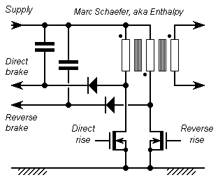
Greater numbers of shorter pulses need even less power. Here the current shall increase for 5ns and decrease for adjustable 50ns. The coil can keep the same shape as for 1µs but now thick rod or tube is good enough. The turns are now in parallel to reduce the voltage to 100V; or several generators can feed each a part of the coil; or the coil can consist of one single very broad conductor, preferably broader at the return leg, and accept a slightly smaller voltage. Over 5ns, the total current increases to 3.6A only. The outer turns will swallow more current than the inner ones, which isn't bad for the induction pattern; to avoid this, put the turns on a square pattern (or hexagonal, etc) near the target zone, instead of side-by-side. The fast main switch is a dual MOS meant for RF transmitters, like the BLF884P. Their supply is at most 50V, brought to 100V by a 1:2 transformer which also produces bipolar pulses. Braking through the diodes reinjects power in two special lines; the one that shall not brake is just fed over twice the supply voltage - this better design works for longer pulses as well. Some diode-capacitor pump can preload the braking lines, while voltage regulation defines the braking time. A few Zener chosen by transistors could dissipate the small power. The diodes could be SiC Schottky like the C3D08060A. These would contribute 4W of the 7W switching losses at 70ns period, and to nearly all 4W conduction losses. These diodes begin at 600V in a LF package; a better fit would be welcome. The HF electronics is at the coil, and the power and control cable is now easy and lightweight. Marc Schaefer, aka Enthalpy
-
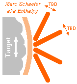
Here is a coil enabled by the smaller current and induction: neither round nor flat. The turns are packed close where the effect is sought, and spread apart elsewhere to reduce the inductance. Usual 8-shaped coils induce undesired potential gradients nearly half as strong under their return paths as under the central zone; the coil sketched here shall minimize them by placing the return paths farther away from the cortex, but near enough to reduce the effect of the main current path outside the central zone. The angles of the turns (possibly more than 4, possibly of different sizes and shapes) should hence be optimized. I won't do it; a small software needs only to sum over the current path the contributions to the vector potential A to various positions at the target. The Biot and Savart formula is here, and in http://de.wikipedia....t-Savart-Gesetz The active zone being ~45 mm long and the return paths ~85 mm, I estimate the inductance to 560nH with for instance 4 turns, using 4*500 nH/m where the turns are grouped and 1*500 nH/m where they're spread. To achieve the same 2,9 GA*turn/s as the 2* D70mm coil from Magstim fed with 2800 V, the design example takes only 725 MA/s and 406 V, and if the pulse's active duration is just 1µs, the peak current is only 725 A. Power components may prefer more turns. The coil's wire consists for instance of commercial Litz wire of 33*Awg41 or 71µm individual wires. 7 such threads are twisted to a strand (for 2m in a lab, fasten them to the ceiling, put weights, and turn) and 7 strands to a conductor of 6.4 mm2 in D~4.5 mm, filled to 40%. Over the coil, 1.5 mohm DC resistance lose 2.8 mJ over one pulse of 1+10 µs * 725 A, while eddy currents lose roughly 1.6 mJ. Copper weighs 30g, so if hundred 1+10 µs pulses are one 0.1+1 ms pulse worth, the coil can absorb 2000 equivalents in 80K heating. The cable may use the same 7*7*33* D=71µm conductors; 4+4 of them, insulated and braided, plus shielding and mechanical protection, make a 2 m bipolar cable. Copper weighs 0.91 kg; 2.8 mohm DC resistance loses 5.4 mJ and eddy currents some 1.8 mJ. The coil plus the cable lose 15mJ from a 150mJ pulse. Aluminium Litz wire would be highly welcome. A pair of Toshibas's MG300Q1US51 - and certainly others - look capable of switching the pulse: 1200 V, 300 A, tr=50ns tf=100ns. The forward mode would reduce conduction losses in the IGBT. Regenerative braking reduces the supply's capacitors to ~1 dm3. Marc Schaefer, aka Enthalpy
-
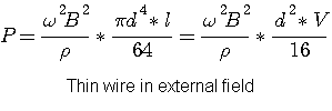
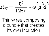
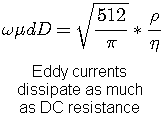
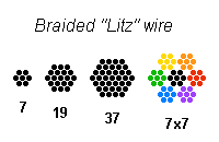
Here are the losses I computed for eddy currents in wires, because these predominate if thick wire is used at moderate or high frequency. Omega is 2*pi*F B the RMS induction rho the resistivity (18e-9 ohm*m for cold copper) d the diameter of individual wires D the diameter of the bundle l the length and V the volume of the conductors eta the filling factor mu the total permeability (pi*4e-7 H/m for vacuum). A wire, thin enough to let an external field pass through nearly unchanged, dissipates as (provided I didn't botch it, of course): A round bundle of thin wires that creates its own induction dissipates as below. This holds approximately for an annular coil BUT beware it's for 1 turn... Multiply by the turns squared. Note losses don't depend on the bundle's diameter. The limit where eddy currents lose as much power as the DC resistance does is below - still when the bundle creates its own induction. It can be worse with a magnetic core, especially near an air gap. The parry to eddy currents in conductors is a braided wire ("Litz wire") composed of insulated thinner wires twisted together. Round wires can occupy this fraction of the cylindrical section at best: 7/9 ~78% for a 7-wire Litz 19/25 ~76% for a 19-wire Litz 49/81 ~60% for a 7*7-wire Litz, and so on knowing that a cylindrical section occupies at best 79% of the winding area of a coil. This is how typical sections of Litz wire look like, with 7, 19, 37 and 7*7 twisted wires: Marc Schaefer, aka Enthalpy
-
An airship that can adjust often and quickly its buoyancy would be good for sightseeing tours. Presently, they adjust the ballast to the passengers, a rather lengthy operation needing people on the ground. These airship are rather big and carry a dozen of tourists for hours. An alternative is a turbine helicopter that takes two passengers on a shorter tour, but it's pretty expensive. Imagine the operation of a small airship with my regenerative buoyancy control and maybe silent electric propulsion: take a pair of tourists, make a turn around the Pão de Açúcar (or the Iguazu waterfalls, the Taj Mahal, Angkor Wat... There are many candidates), land after half an hour, take the next customers. Marc Schaefer, aka Enthalpy
-
Fun, that's less than 10 atoms. Thanks for the link! I believe to remember that catalyst cost, or simple availability, can still be a limit. Not for iron, but things like rhenium. Wetting nicely the whole catalyst area would be an advantage in such cases. What remains is the uniform thin liquid film. If the disks are catalysts or reactants, the intermediate compounds (carbenes?) in the liquid are produced near to the gas. A stack of spheres would do it less uniformly, say where the drop leaves the sphere. The adjustable rotation speed of the disks gives also more control than a seeping liquid. ======================================= Wipers, standing brushes or mobile brushes, liquid jets... can wipe away from the disks reaction products or poisons that would slow down the reaction or bring other unwanted effects, maybe undesired further reaction steps. This can be done for instance where the disks enter the liquid bath. One thing a stack of pebbles can't do. Ah! Marc Schaefer, aka Enthalpy
-
Thought further about this puzzling question... I'm convinced now that the aim of the nozzle is to bring a big throughput or air in a small volume to counter the heat losses and achieve a hotter zone. For that, a convergent taper is better than a narrow cylinder, because slower air at and near the inlet loses less pressure. It is also better than a short small hole, which reduces the throughput exceedingly because the air jet continues to contract after the hole's smallest section. The slowly convergent taper, as one benefit more, produces a flow with little added turbulence and losses, thanks to the pressure gradient. The optimum is between a wide section kept as long as possible and a slow taper. Not having my Sigloch at reach, I suggest to begin with existing cone angles http://en.wikipedia.org/wiki/Bellows http://en.wikipedia.org/wiki/File:English_Bellows.jpg and experiment 2-3 angles around this value, which can't be very critical. A sharp end at the outlet is better than a round one, if ancient technology permits it. This separates the free jet neatly.
-
Keep it in airtight containers. The only method I see. When moving it from one tight packing to the next, be quick, and work in dry air, maybe within a glove box with dessicants.
-

Magnetism propagation / attenuation in iron ?
Enthalpy replied to Externet's topic in Classical Physics
No simple method, because the flux leaks over the whole length or the ferromagnetic bars. You have to evaluate the reluctance of the circuit between the bars, and combine it with the magnet's behaviour, which can be simple (ferrite, Sm, Nd) or not (Alnico). It gets simpler if the bars have a high permeability and don't saturate. If you're lucky you can neglect the flux around the magnet that doesn't pass through the bars, and the flux at the far end of the bars. You've grasped here the difficulty of magnetic circuit design. It doesn't resemble an electric circuit, because no insulator is available here, so fields must be created right where they're needed. It resembles making electric circuits in the Ocean. All designs depend on that. For instance, the coils of a transformer are concentric instead of using one iron leg each. Or the stator winding of a motor or generator is around the rotor winding or very near to the air gap, and not farther away where more room would ease the design. This is what Gramme design improves radically. Type I superconductors would be DC "magnetic insulators" (see Meissner effect, for instance at Wiki) but only for inductions of few mT. In HF, conductors block magnetic fields, but the shallow currents that do it mean losses. -

Motion of a charged particle in a magnetic field.
Enthalpy replied to Physicsinator's topic in Classical Physics
I hope you don't imagine the spin that way, do you? -
Fluid dynamics is seriously complicated, alas. The difference you notice between 100mm and 600mm length results from viscosity and turbulent motion, so no simple law like Bernouilli will tell you. CFD need a computer, a software, detailed information about surface smoothness etc - and a strong faith in the output of a software... Fortunately, scientists have studied fluid dynamics, and found empirical laws. Still not easy, and need some learning, but usable for hand calculations, with reasonable results. If you read German (I haven't seen any translation), the best usable book I know is: Sigloch - Technische Fluidmechanik Typically, you have to compute dimensionless numbers like Reynolds and get relations with experimental powers of these numbers. The optimum diameter is "as big as possible at both ends" if you just wanted to minimize the pressure drop, and the optimum length nearly zero, so I suspect an other effect is sought, like the faster and hotter combustion of coal obtained by turbulence or by a a fast jet, as you can observe in a barbecue. In this case, the smaller end should be at the coal, and the angle not very steep - 100mm suffice between 35mm and 20mm, and (35/20)^2 suffice to lose little pressure at the D=35 inlet. You would gain more by rounding nicely the inlet. Looks reasonable to me: because of heat losses, you get a hotter combustion if air is brought faster in a small volume, so this must be the desired effect. Now we're full in a nozzle, and the cone does make sense, though it's not the only possible shape.
-
Could it be that the pellets are sintered from powder? If sintering is done shortly, with less pressure, or at a lower temperature, it leaves porosity. That's a standard way to obtain porosity in ceramics, metals...
-
In fact, both operate much alike. Thinner and uniform liquid film? Even smoother operation? Horizontal? Ah, yes: if the solid surface is coated with an expensive material like a precious metal catalyst, disks are easier to coat and make better use of the area. If the solid area is a catalyst or one reactant more, the better controlled thin liquid film provides a shorter and better reproducible path to the gas.
-
Possible and done. Ice near 0°C is molten by pressure, hydrogen gets metallic, ice changes its crystal form... Changing from gas to condensed phase is much easier, since the pressure acts on a bigger volume change.
-
Researchers consider something similar that has a better outlook than calcium hydroxide. Silicates of metal would be reacted with carbon dioxide to produce silica and metal carbonate, which are both solids. Or some intermediate combination os silica and carbonate.
-
Normal people get liquid nitrogen from sellers and let it evaporate as needed. It's naturally clean, cheap. Borrow some from the next university or lab. You might obtain it gaseous in a pressure bottle as well. I wouldn't consider chloramine as safe, since it's a precursor to hydrazine. Nitrite neither.
-
Consist of three quarks and gluons. The additional particles observed in a collision at the LHC are created from the kinetic energy.
-

Metal Atoms & flow of electric current through them (mechanism)?
Enthalpy replied to chandragupta's topic in Quantum Theory
Further thoughts: Inner electrons are generally considered immobile, with only "outer" electrons contributing to the current. Shared electrons not only jump from one atom to the next. Even before any electric current, they are shared by all the atoms in the piece of metal. A piece of metal can be viewed as a single molecule. Mobile electrons in a solid do not behave as in vacuum. Especially, their mass differs, and can also be negative, which lets them behave unexpectedly in the Hall effect. People introduce then "holes" with a positive charge and mass as these behave normally and allow simpler reasoning. -
You might assemble smaller flat panels to make the paraboloids. They could consist of triangles of plywood screwed on a wooden truss. It even burns. 3400Hz suffices to transmit voice (like telephones, corresponding to 100mm wave length. +-15mm accuracy is enough. Have some means of measurement and adjust the screws at the truss to 5mm, then the curvature must stay within +-10mm. Take 15m focal length (define precisely where the users must stand!) or 30m curvature radius, then the triangles can have 0.55m radius or 0.95m base or 0.39m2, so your 177m2 reflector needs 454 triangles and half as many adjusted holding points. Well, not so nice after all. ================================== You parabola can be a sphere. At 15m focal length and 15m diameter, the discrepancy is only +-1.5mm; a shorter focal length is possible. This enables to build a tripod and check the reflector's shape with a string, or perhaps shape a sand reflector with a vacuum cleaner at the string, then use the sand form to produce the dishes. not really easy. ================================== If you use centrifugal force to shape the parabola, rotate at 1 turn in 10.8s to get 15m focal length. Cast concrete, rotate, wait until it hardens. How to rotate hundreds of tons? You find it. ================================== The dish's material could be cotton impregnated with wax or paraffin. At least, it burns cleanly. ================================== If you have 45 sectors (at least near the rim) instead of 12 then the panels can be flat between them. You could force plywood with screws to follow the spokes' curvature. Did you consider the effect of wind? Your reflector is a huge sail.


