-
Posts
3887 -
Joined
-
Last visited
-
Days Won
1
Content Type
Profiles
Forums
Events
Everything posted by Enthalpy
-
Yes, both bell bronze and invar are lighter than the sum of the constituents' volumes let compute. I did the computation. Don't mistake bell bronze for other compositions, and remember that nickel is denser than iron. I don't know if absorbing hydrogen must release energy. A dissolution can release or absorb energy. 1% of the combustion heat of hydrogen would be a lot for a low-energy process, for instance the evaporation of hydrogen at 20K absorbs only 916J/mol while the combustion releases 286kJ/mol. Anyway, 60kW is as much heat power as a petrol engine releases, and cooling it is long solved. It doesn't need me. And did you check how lukewarm the storing metal gets when absorbing hydrogen? Even if 1mol metals stores 1mol hydrogen, released 1kJ/mol heats only by 40K, so cooling may not be necessary during filling.
-
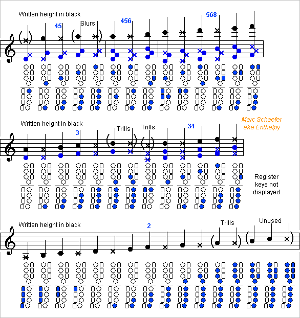
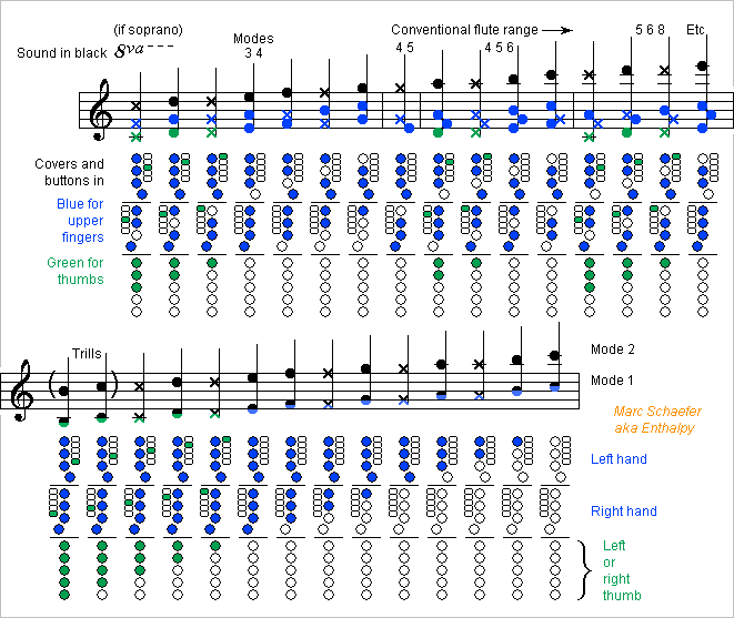
Here's a system with simple keyworks for the Soprito, the piccolo reed instrument that plays on its higher modes, about a seventh or octave higher than written. This system has only one tone hole per halftone position and independent keys. Most fore fingers operate two buttons and covers. The covers are closed at rest except the four lowest, so the musician lowers fewer fingers, which eases cross-fingerings. The fingers can operate the button pairs at different phalanges or both with the tips, as suggested there https://www.scienceforums.net/topic/107427-woodwind-fingerings/?do=findComment&comment=1060629 experiments shall decide. The thumbs move no cover but about four duplicated register keys not displayed on the drawing. These fingerings are expectedly as difficult as the flute's one. Marc Schaefer, aka Enthalpy
-
Most concert flutes have a low natural B presently so my system must have it too. Rather than adding an optional sixth synchronized cover at the foot joint, it's better to shift all keys and fingerings a halftone lower and have the low B on all instruments, as it serves for trills. Here's the fingering chart, updated from Jul 02, 2017 here: All qualities are kept, including easy slurs and trills using the standard fingerings on both lower octaves, and perfect cross-fingerings for all notes, including the third octave F#, G#, Bb, B and further in the fourth octave. The 7th and 9th modes could be added. Maybe we can have a register key for the first five notes of the second register. With its long button along the five thumb buttons for simultaneous use, and a tiny hole. Marc Schaefer, aka Enthalpy
-
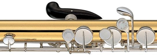
This is an example of a hand rest on a flute, gratefully pinched from the bass YFL-B441 For the systems I propose, where both thumbs must move freely, it can inspire both hand rests at the flute. Some non-horizontal instruments may need an adapted shape.
-
One Mn-Cu alloy is well documented: the M2052, with mass% Mn-22.1Cu-5.24Ni-1.93Fe. Its density is 7250kg/m3, 5% less than 7628kg/m3 if adding the constituents' volumes. Its Young modulus is also 47GPa instead of 198GPa of Mn and 130GPa for Cu. But it's a vibration damper, as opposed to bell bronze and invar. Besides providing room in the lattice for hydrogen (just a hypothesis), it has two transitions, one below and one above room temperature, which might help release the hydrogen. Ni and Fe serve mostly to adjust the transition temperatures. Marc Schaefer, aka Enthalpy
-
Data about materials' internal damping is scarce, especially for the frequencies and strains common in wind instruments. In P2Q2=E'Ik24*psi2, Q may be 50 for a damping metal, P=500Pa for a flute hence P2=50Pa for the elliptic deformation near the tone holes as computed here scienceforums on Nov 26, 2017 and k2=210rad/m for a D=19mm tube, so E'Ik2*psi2=P2Q2/k22=0.057N*m/m, and for a 0.45mm tube, the strain is 17ppm and the stress 1.7MPa (0.25ksi). The strain is much smaller for the resonances that bend the tube. It's stronger for a saxophone and with materials that damp less like brass or German silver, and it's much weaker for thick wood walls. Resonances at 100Hz to 5kHz matter more to music instruments. ========== For wood, Mankind has the already cited PhD thesis by Iris Brémaud (in French) https://hal.archives-ouvertes.fr/tel-00548934/document with a table of stiffness, damping, density on p117 (Pdf p141). Measurements were done by resonating a 360mm*20mm*20mm beam, hence at a meaningful frequency. I wish data existed for bending across the fibres, which determines the elliptic deformation of woodwind tubes. Tan=0.57% for Dalbergia melanoxylon isn't much, but thick wood is stiffer than metal against elliptic deformation. ========== The Dtic 486490 document compiles many sources, reproduces curves and data for varied materials, and is openly available (thank you!) http://www.dtic.mil/dtic/tr/fulltext/u2/486490.pdf Copper and its alloys, including cupronickel, brass and bronze but not German silver, are on p72-76 (Pdf p98-102). Damping is very small, 10-4 to few 10-3, and its dependence on temperature and stress suggest it's even smaller for an instrument's tiny stress. The shape memory alloy Cu Al12 Ni5 Mn2 Ti1 measured in Dtic A218801 damps strongly but seems difficult to use at music instruments. Silver, pure and alloyed with Cd, In, Sn but not Cu was measured in "Internal Friction and Grain Boundary Viscosity of Silver and Binary Silver Solid Solutions" by S. Pearson and L. Rotherham the already cited Dtic 486490 reproduces the curves on p102-103 (Pdf p128-129), where damping is very small at these very low frequencies. Obviously "sterling silver" differs to sound poc-poc at flutes. Whether the usual copper makes the magic, or something else? The high-damping Mn-Cu alloys, especially the M2052 Mn Cu20 Ni5 Fe2, was measured against amplitude and frequency, there https://www.jstage.jst.go.jp/article/matertrans/42/3/42_3_385/_pdf/-char/en Fig.4 tells tan=3,7%-2,2% at 200Hz-5kHz and 20ppm. Excellent, but the alloy corrodes, and annealing can't restore all the damping after >5% cold deformation. Many Co alloys like 20Fe, 23Ni, 28Ni or 35Ni show high damping on p69-72 (Pdf p95-98) of the already cited Dtic 486490, but this demands a strong strain of 10-4. Worth a try, especially at saxophones? Co-Ni is easily electroformed to intricate net shapes, annealing should achieve the shown properties. Mo should be easy to co-deposit, Fe too, see here scienceforums on Sep 29, 2018 2:24 pm a magnetic field <40kA/m (<500 Oersted) ruins the damping, and wide thin parts concentrate the 30A/m geomagnetic field. This isn't extremely critical, and maybe some alloy has a low permeability, or if a layer of Co-Ni is deposited on a core, it can be interrupted at short intervals, and a pattern like zigzag still give stiffness. Some thin layer, usually Ag, can protect against contact allergies. Sharp grooves perpendicular to the strain, like from rough sanding, would concentrate the stress and increase the damping. Cheap to try at least. ========== I tried to reproduce by software the ting and poc I heard long ago when tapping flute headjoints with a small plastic part. Here TingPoc.zip TingPoc_A_GermanSilver.wav plays an exponential decay of 100ms, 80ms, 60ms at 3100Hz. I feel 80ms reproduce the German silver sound, telling Q=800 and 1/Q=0.13%. This includes damping by sound radiation and by viscosity. TingPoc_B_SterlingSilver.wav decays with 50ms, 20ms, 10ms, 5ms, 2ms at 2300Hz. With 20ms I still perceive a duration, so sterling silver must decay with 10ms at most - I didn't even hear a height, so it may have been much shorter. Viscosity and radiation are identical, so sterling silver itself brings Q<=70 and 1/Q>=1.4%. The softer shock on silver didn't prevent ringing, I believe. The ratio of yield strength, 120MPa vs 500MPa, is too small, and the plastic clapper was soft. It would be interesting to try with the Pcm alloy. Marc Schaefer, aka Enthalpy
-
Oops. In my last message, paragraph " With the resonances ..." please read 5*10−13m3, sorry.
-
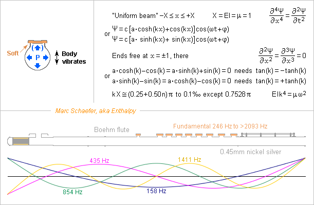
Flexural resonances of a woodwind body, quantitatively. Here for a Boehm flute, of 0.45mm German silver (Cu-Zn-Ni alloy), with B footjoint. ========== I model the body by a uniform cylinder. µ=0.31kg/m, 30% more than a naked tube, to include the stiff parts of the keys. EI=183N*m2. The cylinder has proper flexural modes at 158, 435, 854, 1411, 2108, 2944, 3919, 5034 Hz and more. This is within the fundamental and low harmonics range of the flute. The heavy cork could be represented by extra tube length, or better, its lumped mass included in the model. The tone holes reduce the stiffness. The joint fittings are supposedly less stiff. So the evaluated frequencies aren't accurate, but the result stands: resonances in the playing range. ========== The covers move by estimated 0.1mm when the musician varies the pressing force by 0.5N (from 50gf to 100gf) so the pads are 5kN/m stiff. The covers weigh estimated 3g, so at the Eb and Ab holes they resonate around 200Hz, and above that damped resonance they behave like a mass. The other covers are pressed down by fingers that add mass and the resonance is lower. So for all the tube resonances within the playing range, the covers transmit to the tube little of the oscillating force exerted by the air column's pressure. The covers don't balance the force exerted directly on the tube. The tube receives a net lateral force. As well, the pads are far less stiff than the tube. A side force at a second mode's antinode bends a beam 123+123mm long which is 1.2MN/m stiff. The pads can at most limit the tube's resonance. ========== For instance the third bending mode around 854Hz has a half-wavelength of 93+93mm so it's 2.8MN/m stiff to a force at an antinode. The flute has two covers near both antinodes of the bending mode and the air column. In front of two D=13mm holes, 1Pa pushes 0.27mN which would move the tube by 95pm without resonance. As the covers don't follow, the tube's movement adds pulsating 2.5*10-14m3. We can compare with 0.42m air column containing 120cm3 where the 1Pa induces 4.2*10-10m3 compression as a mean over the arches. With the resonances, the effect is significant. Just Q=20 for the metal (damped by the pads, the hands and more) produces 5*10-14m3 instead, and at the resonance it's a loss rather than a capacitance. If the other losses at the air column leave it Q=200, the tube's vibration drops it to Q=160, a significant and perceptible difference. ========== Silver, while less stiff than German silver, damps the vibrations far better. If tapping a headjoint with a light plastic part, it sounds "poc poc" instead of "ting ting". This reduces the tube's vibrations hence steals less power from the air column's resonance. According to this model, a silver headjoint brings some damping to a resonant main joint. But to a silver main joint, the headjoint material matters little, as I observed (here on Nov 07, 2017) http://www.scienceforums.net/topic/111316-woodwind-materials/?do=findComment&comment=1022242 Silver keyworks damp their own resonances, which must be excited by the tube's transverse movements - but by how much? Dalbergia melanoxylon (grenadilla) offers E=20GPa along the fibres and rho=1310kg/m3, so the tube resonates at nearly the same frequencies as German silver. Its intrinsic losses (tan=0.6%) outperform German silver but probably not sterling silver. The usual thicknesses make the tube about as stiff as with metal. But thick wood improves the oval deformation I described here on Nov 13, 2017 http://www.scienceforums.net/topic/111316-woodwind-materials/?do=findComment&comment=1023070 Dalbergia retusa (cocobolo) brings only E=11GPa for rho=950kg/m3, so it has more resonances than grenadilla, and these are stronger, as tan=0.9% can't compensate the lack of stiffness. Buxus sempervirens (boxwood) has only E=9GPa for rho=930kg/m3 but tan=1.5% is better. It made clarinets before exotic wood became available. Unloaded plastic has bad E=2GPa for rho=1050kg/m3. Expect 3* as many flexural resonances as with grenadilla. Only damping helps, hence the choice of ABS or PP. PMMA cumulates bad damping, as already heard at an oboe. Stiff and damping materials give reed instruments more blowing resistance and make them louder. All is consistent with the usual claims about woodwind materials. Cu-Mn alloys bring high damping, are cheaper than silver but unusual and they resist corrosion less. Worth a try. Reinforced plastics can offer 18GPa for rho=1200kg/m3 with 30% of short graphite fibres. As good as wood, and better in the transverse direction. The difficulty is to damp the vibrations, which graphite fibres don't. Aramide fibres would but they're difficult to machine. Hence my hope with polyketones, or maybe ABS. ========== I'm convinced that some luthiers know much more about theoretical acoustics than university science does. Anyway, I haven't seen the model I propose in academic books nor papers. This explanation has been sought for a century and a half. Now that I know an explanation, I'll surely notice the effect far better. Marc Schaefer, aka Enthalpy
-
The flexural resonances of the body explain decently the material's influence on a woodwind. The air column's oscillating pressure creates a force on the tone hole covers, but their pads are soft and don't transmit the force to the body. This holds above the covers' resonant frequency, which is well within the playing range for a flute. Then the radial force on the tube is unbalanced where the cover doesn't transmit its fraction. The resulting lateral force lets the body vibrate. It has many resonant frequencies within the playing range of a flute, and if the metal resonates strongly like nickel silver does (as opposed to sterling silver), then its movements versus an immobile cover create a volume oscillating in phase quadrature with the pressure - a loss. Notice that the own movements of the covers versus the tube create losses too, better known already, which isn't my point here. This parasitic volume is smaller than the admittance of the air column, but it contributes much to the otherwise small losses of the instrument. Quantitative explanations should come for a Boehm flute. I expect this process to matter for all woodwinds. Marc Schaefer, aka Enthalpy
-
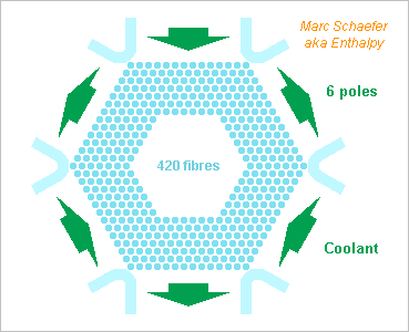
420 fibres fit on a hexagonal pattern 13+1 fibres wide, not 8+1. The coolant poles are 2.3mm wide, so if keeping 5.6m/s there, 75dm3/s flow through the bundle. 300bar gaseous hydrogen exits 1.6K warmer at the pole centres so the phase mismatch between the fibers is smaller. The bundle could be upscaled, for instance by *32 for 530kW light at identical hydrogen speed, and more with faster hydrogen, as the fibers accept a stronger force. ========== I use data from these sources: nvlpubs.nist.gov silica's n versus T and P springer.com silica's n versus doping brennen.caltech.edu aerodynamic drag
-
Yes. My parents still had an icebox for camping when I was a kid and the last ice age had just finished. A mobile seller brought water ice or carbon dioxide ice. Cooling a whole house is a bigger scale, like 700W mean cooling power, maybe 20* more than a fridge. Electricity for a fridge is cheap and it achieves -8°C in the freezer, but air conditioning for a house is expensive, it heats the whole city, and emits significant carbon dioxide indirectly. The whole challenge is to make the commercial activity sensible now despite it was abandoned half a century ago. For much bigger amounts, with better machines, and good organization. Frequent deliveries by truck might become a nuisance, I hope electric motors make the moves more acceptable. Sawdust was a damn good idea, but I doubt we found the proper amount for an ice dump 1000m long, 190m base, 90m high. My best guess is a cheap, abundant material found everywhere - sand, even though a fair insulator. Fortunately, the size eases insulation, due to volume versus surface. Happy to have your approval! As for moderating the temperature of the blown air, see my: "Regulators in the rooms suck as much cold air as needed locally, they blow and mix it as needed" there https://www.scienceforums.net/topic/116226-iceberg-to-capetown/?do=findComment&comment=1073797 Sure. But as things look, bringing a complete iceberg or storing ice from a lake is cheaper and takes far less energy than producing the ice, so I have more intellectual appetite for the more ambitious option. The consumer's investment is also cheaper if using ice already produced. The storage tank could even belong to the ice supplier or be leased like cell phones are. To offer a completely new operation, I imagine that the supplier must provide all the elements at once.
-
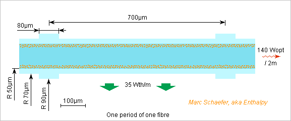
Oops : e-6~1/400 coupling by the evanescent wave through 120µm coolant needs transverse j50krad/m that demand 1.45-1.449 96 difference between the refractive indices, impossible to stabilize. ========== Cooling figures The following figures aren't optimum nor well chosen. They shall only shaw that some set of parameters looks feasible. I use data from the silica family, but fibre lasers prefer aluminosilicates. Gaseous nitrogen seems easy, but I compute with gaseous hydrogen. Colour centres can work under the synchronization sections too, as the overtemperature is small. This eases the manufacture. I compute with an even distribution through the core's depth, but concentrating them near the cladding as depicted would even the core's temperature hence light intensity and is made by just one deposition step more. The sync sections can share the cladding's material. Or maybe use the core's material, but then phase shifts happen. I suppose the fibre can receive the thicker cladding everywhere and be etched thinner outside the sync sections. A smooth surface matters: heat again? Sources don't tell it, but I guess some lossy material is needed around the cladding to force the single mode. Here it needs an intermediate low-index material in between. The low-index and lossy materials must be absent from the sync sections. Remove them mechanically? That's easier if they are organic. Or deposit them after the sync sections are assembled? I hope the sync sections can be sintered together, or maybe glued. Electric sealing would need Na+ ions to my knowledge. Gaseous hydrogen at 300K 300bar has compressibility Z=1.19, 10110mol/m3, 20.4kg/m3, capacity 28.8J/mol/K 14290J/kg/K 291kJ/m3/K, viscosity 9.7µPa*s and 0.48mm2/s. 420 fibres, 2m long, shall deliver 420*140=58,8kW light and produce 420*70=29,4kW heat. The sides of a hexagonal pattern are 8+1 fibres wide (err, no, it's more), or 1.6mm. 54dm3/s hydrogen exit 2K warmer, so silica fibres whose index drifts by 8.7*10-6/K propagate 1300nm light over 700µm with +-2.5° discrepancy to be evened out by the sync sections. Hydrogen flows at 5.6m/s at the 3*2m*1.6mm ports and some 13m/s between the fibers. If the fibres didn't interact, then Reynolds ~1600 makes the flow transitional and Cd=1.0. Tripling the drag without reason to account interactions, the flow pushes 0.14N/m on the fibres. Stiff supports with 700µm period leave 5.5nN*m bending moment, so R=70µm and E=90GPa give 0.4nm deformation and 20kPa stress. The experimental 0.32 gauge factor over the volume changes the refractive index by <70ppb only. 1.4W/m/K silica conduction from r=0 to R=50µm and uniform 35W/m per fibre make the centre 2.0K warmer than the interface, so the index 17*10-6 bigger amplifies the field by <2.0 over the outer 20µm radius. The algebraic solution would be better, and colour centres only near the interface would give uniform temperature and field. From r=50µm to R=70µm, the temperature drops by 1.3K, the index by 12*10-6 and the field by <1.4 more than what both materials do. The coolant resides some 8µs around each fibre so heat diffuses only 3µm deep, and turbulence shouldn't reduce that further. This coolant layer warms by mean 3K and this won't differ much among the fibres. Arbitrary exp(6)~400 field attenuation over 2*40µm thick sync sections needs a transverse wave number j75krad/m. Indices of 1.45 et 1.450 080 achieve that, needing for instance 0.05mol% GeO2 doping at the core, and possibly some compensation of the colour centres. Marc Schaefer, aka Enthalpy
-
The thermal conductivity of dry sand is rather 0.25W/m/K, so over 300 days, 1m thick sand would let melt only 3% of the the 1000m long, 190m base, 90m high ice dump suggested on September 30, 2018. Sorting the sand to keep only one grain size may reduce the thermal conductivity. ========== Some places like the North American Great Lakes region have icy winters, hot summers and a rich big population. Insulated dumps can keep ice from winter to summer to sell for the already described air conditioning. One source of ice could be the lakes themselves. Distribution of the ice is again a significant cost contribution. Suburbs, near to the ice dump and where trucks circulate better, ease that. The many short rotations enable electric trucks easily. Swap the batteries if necessary to save time. Marc Schaefer, aka Enthalpy
-
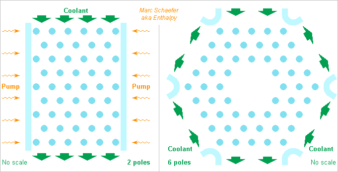
This illustrates coolant flowing transversally among the fibres: With two "poles" (similarly to an electric machine) and pumping illumination from the sides, or six coolant poles and pumping unspecified. Notice the lack of fibres at the centre where the coolant stagnates. A powerful laser needs much coolant throughput, transverse flow eases that. ========== An evanescent wave through the coolant may be possible but is not easy. Imagine the evanescent wave at vacuum 1330nm shall decrease by exp(6)~400 over transverse 120µm in the coolant. That needs transverse k=j314krad/m in the coolant. Propagating in silica at k=6.850Mrad/m from N=1.450, it needs 6.843Mrad/m in the coolant, or N=1.448. Coolants with a matching index exist (N=1.449 for CCL4, mix it) and some will be transparent enough, but the index drifts with temperature in silica and in liquids. The close match must be kept despite heating. Surrounding a fibre core with a material of similar composition, like a bit of fluorosilicates added to silica, keeps more naturally the tiny index difference over temperature. Marc Schaefer, aka Enthalpy
-
A first pumping scheme uses one fibre laser to pump each fibre of the multifibre laser. The pumping light arrives in the narrow multiple lasing fibres, with single cladding or no cladding. Coupling by the evanescent wave is easier, and cooling the multifibre laser has no additional constraint by the pump. Fibre lasers are already common. Just build many independent ones and cool them. The multifibre laser receives pumping light, for instance at 1µm, that is not coherent from one fibre to the other, and makes light, for instance at 1.3µm, that is coherent across the fibres and can be well focussed. A good power efficiency for this step resembles the wavelength ratio. The pumping fibre lasers had already converted light from laser diodes which themselves received electric power. Two pumping lasers per fibre, one per side, make sense too. Splitting or merging the pumping light is also possible if somehow advantageous. Marc Schaefer, aka Enthalpy Thanks Swansont! Source?
-
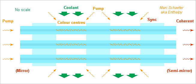
Hello everyone and everybody! Fibre lasers produce a high quality beam up to very few kW output and with excellent power efficiency. Nice to cut steel sheets for instance. But 2kW in D=100µm and er=2 make already 7MV/m, and the material's breakdown doesn't allow much more. To obtain more power from several fibres and keep the phase coherence among them, I propose to synchronize the phase by evanescent waves. With a cladding thinner than usual, fibres side-by-side share some light, and if done often enough while the laser light is produced, I hope the bundle emits coherent light. This shall be easier than a single oscillator driving independent lasers amplifiers before merging the beams, which needs difficult precautions to limit the phase drift over the long amplifiers. The fibres alternate a certain number of amplifying sections, with colour centres and dissipation, and synchronizing sections where the evanescent wave drops slowly enough to couple the fibres. Short distances between synchronization avoid excessive phase discrepancy. If the coolant has low optical losses and an index close to the fibres' one, it too can couple the fibres by evanescent wave. Then the synchronization sections can become mere space holders. Cladding at the amplifying sections reduces the light amplitude in the coolant and at the interface, if this is necessary against losses. If the synchronization sections or space holders are very short, dissipation there can become acceptable, and the fibres can contain colour centres there too. Pumping light can arrive from any end, or both, or from the sides. The coolant too can flow axially, though radial flow makes a greater flux or a lower speed, especially with four poles or more as in electric machines. Thin fibres are easily cooled. The multifibre laser can oscillate or amplify. The pilot light might sometimes be fed in a single fibre, but I expect it will be spread most often. Mirrors at none, one or both ends are commonly Bragg gratings, more easily because synchronization is done elsewhere. The multifibre laser needs not be straight, as long as the fibre lengths are identical enough. It can build a ring for instance, optionally with several turns. I believe to have described this already on the Net. I someone knows where, please tell! Marc Schaefer, aka Enthalpy
-
No hard limit. It's a matter of diameter, of an angular speed convenient for the other items on the shaft, and of optimization rather than clear barriers. Magnetic materials can operate at kHz, MHz, even GHz (though less useful at many GHz). But over few kHz, the good materials use to be brittle, which I'd dislike at an aeroplane. One can misuse iron laminations at higher frequencies, but at some point the higher frequency becomes a drawback then, not an advantage. Power electronics can still switch efficiently at 100kHz for instance, but in the MW or GW domain, lower frequencies are better. Then you want to switch must faster than the produced waveform that powers the machine, which puts a strong limit. My waveforms are a new solution to this https://www.scienceforums.net/topic/110665-quasi-sine-generator/?do=findComment&comment=1041409 Electric machines improve with the peripheral speed, which is limited by feasibility (in a dam), centrifugal force, and possibly the speed of sound and aerodynamic losses. Presently, a sleeve of hardened steel circles the fastest rotors. I proposed to wind graphite+matrix filaments instead. 50-100m/s is common in 1GW turbogenerators, 200m/s is reasonable with permanent magnets, while variable reluctance can be much faster. A small centrifuge can rotate much faster than 400Hz, but a D=1.3m turbogenerator rotor at 100m/s only achieves 25Hz.
-
With a brush, a machine can work. That' a typical homopolar machine. But you show a measuring loop on the photo, completely static and without any sliding contact. This can't produce a DC voltage.
-
Fraunhofer's storage spheres pump water out of pressure-resisting constructions. They need some material (typically concrete) to keep the vacuum. A seducing aspect of the underwater bags is that, to store compressed air at depth, the bladders resist no pressure at all. So to say, the Ocean's pressure keeps the air under pressure in the bag. Though, underwater bags need some weight to stay in the depth. Unless the installer finds heavy rocks or sand at the seabed, he'll have to bring concrete, and in significant amounts too. One other aspect is that water is easier to pump and turbine with decent efficiency than air to a high pressure ratio, and better, storage in the spheres can transport just electricity to and from the depth. ========== Build extra production capacity: sure. When storage is obviously too expensive, this is a part of the solution. Wind electricity is already cheaper than nuclear one and is continues to get cheaper, so more wind turbines are affordable. The other part of the solution is to transport electricity. Between Scotland, Greece and Romania, the distance covers one depression width, so we won't lack wind at all locations simultaneously. Even from Scotland to Galicia, we won't have under 5 Beaufort at all locations for more than one day.
-
And where is the second body when the electron and positron have already disappeared by annihilation, two gamma rays propagated, and one electron detects a gamma ray? Or if you prefer fields with many photons, send a radio wave to the Moon for reflection there, receive it back on Earth two seconds later. In the meantime, you can wrap the emitting antenna in aluminium foil, destroy it somehow, whatever you like. You don't need the emitting item. The receiving item is sensitive to the field that existed after the emitter was made inoperable. Similarly, the receiving antenna can be extracted from an aluminium foil just prior to receiving the wave. If light comes from a remote galaxy, our detector didn't even exist when the light was emitted, and the light source may be a black hole when we detect the light. In such situations, if you want to keep the laws of energy conservation, momentum conservation, you have to accept that fields exist at times when the items that create or sense them are absent. There is more. As light passes by a massive object and gets deflected, light also pulls the massive object, even by that little bit. This is necessary if momentum conservation works. It happens possibly at a time where both the emitter and the detector are inexistent, and at a time when photons are not created nor destroyed. Cumulating all this, one has to admit that propagating fields have an existence independently of the items that create or sense them.
-
Please see my second answer there https://www.scienceforums.net/topic/116226-iceberg-to-capetown/?do=findComment&comment=1071764 I suppose professionals know better answers. Please see my fourth answer there https://www.scienceforums.net/topic/116226-iceberg-to-capetown/?do=findComment&comment=1071764 I consider closing the bottom when arrived. Moving a sac of water in water can be cumbersome. But presently, I prefer to lose the molten water, mine the ice once arrived and transport it solid to the land. Whether storage shall be liquid or solid depends on the use. Bladders have been considered to transport sweetwater over the Ocean. Whether the source is an iceberg shouldn't change much, since melting is harder to prevent than to encourage. You have a whole Ocean full of heat for that. I have doubts about solar energy at 40°, 50°, 60° South. Wind should be more dependable there. Autonomous: I have absolutely nothing against. That's more interesting for smaller transport units. If downsizing to 300 000 t makes economic sense, maybe a hull can replace the bladder, and then movement becomes more natural, including with sails. I have no investors nor plan to earn money with that. That's a reason why I put it on the Web. Feel free to become a billionaire with the idea. Don't forget in your business plan the few technical subdetails to be solved.
-
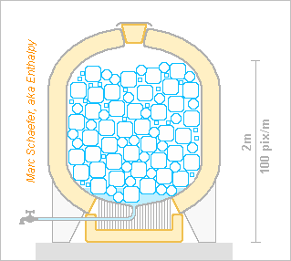
1200kg Ice storage to cool a detached house for a week can look like this: The ice stays in the storage. Air from the house or filtered from the atmosphere or passes through a heat exchanger at the tank's bottom. Regulators in the rooms suck as much cold air as needed locally, they blow and mix it as needed, and the ice melts accordingly. 0.2m foam plus the metal at the top opening leak 43W or 62kg=5% in a week. Flowing the arriving air first around the insulation would reclaim the leaked cold, an opportunity for thinner cheaper foam. The heat exchanger needs roughly 10m2 fins of banal alloy. To clean the exchanger, the foam around it is removable. 2mm steel weigh around 400kg so series production may cost a bit over 1k€ a piece. Some sort of key and measure of the delivered quantity, shared by the supplier and the user, seem necessary. The meltwater can be useful in many gardens. ========== If the ice comprises blocks of very different sizes, more can pack in a tank, just like concrete comprises stones, pebbles and sand. Easily done when mining the iceberg. Delivery trucks, reasonably manoeuvrable, can carry around 25t ice, so they should make a rotation for <<133€, easier than the previous estimate. If a truck makes 6 rotations a day, 20 days a month, it looks feasible, but remains a significant cost share. Marc Schaefer, aka Enthalpy
-
I described here on Apr 08, 2013 an APU that tells how smaller a motor is if it rotates fast http://www.scienceforums.net/topic/73798-quick-electric-machines/?do=findComment&comment=737931 1270kW machine too, but estimated 16kg for 813Hz instead of 224kg for 20Hz. The two-stage gear needs maintenance and weighs a bit too. An intermediate solution, with a single-stage gear and a medium diameter motor, may be considered too. Planetary (epicyclic) gears are compact and powerful at small electric motors. Would they be good for electric aeroplanes? wikipedia
-
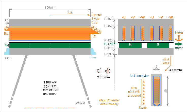
Here's an example of gearless ring motor for the described Dornier 328: 1400kW at 20Hz. 10mm thick Neorec53b magnets (Nd-Fe-B from Tdk) at the D=0.84m rotor move with 52.8m/s and provide 1.16T at +60°C in 2mm gap, of which prestressed graphite composite wound filaments occupy 1mm to hold the magnets. The L=0.16m rotor and 3-phase stator have 24 pole pairs (though differing numbers would cog less). The conductors pass once per pole through an own slot, so the peak voltage is 468V. The magnets are 80% as wide as the poles, so the waveform provides a fundamental amplitude of 1.21*468Vpk. No fractional pitch here, but the slot skew is +-1/7 the pole width, multiplying by 0.967 the fundamental si H1=548Vpk=388Veff and 1400kW take 1203Aeff=1701Apk per phase. The inverter needs inconvenient 1100VDC (if no H3). Multi-turn coils in parallel are more usual and may enable <500VDC, but then only a very symmetric machine avoids stray currents. Fractional pitch would bring known advantages and stay <3000VDC. The bars superimpose 48 flat enamelled e=0.5mm W=6mm conductors that may be lasercut or etched from much bigger sheets for easier turns. I hope to introduce them sequentially in the slots. Estimated with optimism at 0.25m per bar, they show 1.35mohm per phase and lose 5.9kW in total. The 480Hz azimuthal induction in the slots is 0.31Tpk near the teeth, so the eddy currents in the conductors lose 1.4kW in total. I didn't evaluate the radial induction component. The stamped 4mil lamination are of Supermendur (Fe-Co from MKMagnetics) used at 1.87Tpk. This enables three 7mm wide slots per 55mm pole. They lose 40W/kg at 480Hz, or 2.7kW between the slots and 2.2kW outside. All these losses, 12.2kW=0.87%*1400kW, can be conducted away by the bars within 22K if some grease makes the contact with the laminations. Outside the slots, the conductors are spread to cool by ventilation, and they rotate one position in the slot between two slots, as a simpler form or "Litz" (=braided) wire. The stator currents superimpose 94mT at the gap, needing additional 45Vpk in quadrature per phase. The laminations don't saturate. The induction through the slots need additional 71Vpk in quadrature per phase. The machine could be shorter, thicker, lighter. Fractional pitch would ease here. Here are masses in radius order: 54kg Fe-Co external 34kg Cu 68kg Fe-Co between slots 1kg Graphite 25kg Magnets 42kg Steel ------ 224kg Sum The shaft, rings, bearings, casing, fans are not included. More poles would enlighten the motor. Marc Schaefer, aka Enthalpy
-
Ice has more value in air conditioners than molten at a tap. It might also supply +5°C to fridges, but uneasily -10°C to freezers. The former iceberg is too big for that use, and the main cost is to cross the last km to the customer, not the Southern Ocean. de.wikipedia metric, en.wikipedia exotic Every 1000kg=1.09m3 provides 334MJ cold at 0°C, and I neglect the cold liquid's 30MJ. To provide the same, a 350% efficient air conditioner would consume 26kWh costing 5.3€ at 0.2€/kWh. A 40% efficient generator would consume 5.4kg fuel to make the 26kWh - compare with 0.12kg fuel per ton to transport the iceberg from the South. The previous iceberg arriving with 60 000 000 t would be worth 318M€ electricity at retail price and make routine transport very profitable, but it's slightly too big. A rich hot city with 1M inhabitants may have 300 000 buildings with air conditioners that provide each mean 2kWth for 8h a day, 150 days a year: the city consumes 2.6PJth/year. 7 800 000 t ice suffice and save 41M€ electricity. That's an 80m thick, 400m long and 270m wide berg yearly. Bringing net cold to a hot city is more rasonable than dumping net heat to cool the buildings. Over 40km2 at mean 250W/m2, the city receives 130PJth from the Sun over the 150 days. 2K difference? I suppose that a floating bucket wheel can exploit the iceberg anchored at the cost and coveyor belts bring the ice blocks to land storage. Unclear to me. This hardware can serve for several cities and years. Storage would be on the ground, within 2m sand between geotextiles: 1000m long, 90m high, 190m base expose 0.45km2. <1W/m/K and 25K leak <5.6MW. Over 150 days, 220 000 t melt, or 3%. This would apply also if using the iceberg as sweetwater. Every day, a house with air conditioners using mean 2kWth needs 58MJth from 173kg ice. Storage for a week means 1200kg that occupy <3m3 and are only 6.4€ worth of electricity. Carrying 14.4t in the city, a truck should make a rotation for <<77€, not easy. The storage must be accessible from the truck, not by foot over a lift. A D=1.5m H=1.7m tank insulated by 0.2m foam leaks 43W, that's 78kg lost in a week, or 7%. Bigger buildings don't ease much, since trucks have a limited size. A heat exhanger at the tank and few air pipes and fans replace the expensive air conditioner. Marc Schaefer, aka Enthalpy ========== Hi everybody, nice to see that the topic catches the imagination!


