-
Posts
3887 -
Joined
-
Last visited
-
Days Won
1
Content Type
Profiles
Forums
Events
Everything posted by Enthalpy
-
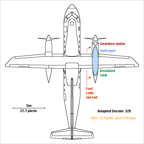
20 to 30 passengers, said Norway's minister, and 90 minutes electric flight. Here you are, with fuel cells, not batteries. It takes limited development, essentially the superinsulated tank I described earlier. The fuel cells exist at least for cars, the motors are nearly banal. With the main gear at the fuselage and engine nacelles under the high wing, the Dornier 328 adapts to fuel cells easily, and its size fits better than the ATR-42. de.wikipedia and (other variant) en.wikipedia Can just the nacelles be retrofitted? 2*1400kW need 2*700kg fuel cells with the Toyota Mirai's performance en.wikipedia Estimated energy needs: 262kg liquid hydrogen in two ellipsoids D=0.9m L=4.6m. 2.2MW*5400s Flight 1.0MW* 600s Taxiing 1.6MW*1000s Divert 100nm @540km/h 1.4MW*2700s Waiting to land Zero Descent compensates ascent? ---------- 17.9GJ Energy at shafts 31.4GJ Chemical energy in 130kmol *60% *95% The motor is a ring D=0.8m gap and nearly 0.2m length, because gears need maintenance, can fail and they weigh too. With some 2*30 poles and sine three-phase, each motor weighs 250kg roughly. This is the estimated mass change from kerosene to hydrogen: -800kg Two turboprops +500kg Two electric motors +1400kg Fuel cells -1300kg Kerosene +260kg Hydrogen +250kg Two hydrogen tanks ---------- +310kg Keep the airframe, take 3 or 4 passengers less. 32 had too little room anyway. The hydrogen and its tanks being so light, more range is seducing. Extra-silent propellers would make sense. Marc Schaefer, aka Enthalpy
-
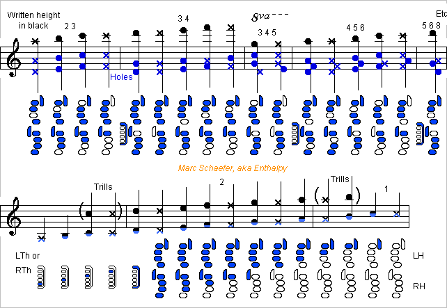
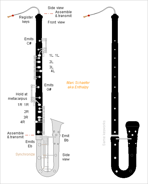
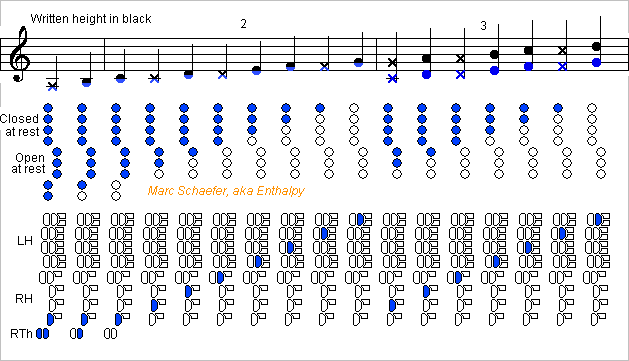
The variant I sketched on Jul 30, 2017 of the even fingerings for oboe and similar http://www.scienceforums.net/topic/107427-woodwind-fingerings/?do=findComment&comment=1004315 makes simple keyworks. Experiments shall decide, but trying to imagine their use, I feel them as convenient as the other variants. So here is a fingering chart for this D variant: Register keys are not displayed. Their number and range must be experimented. Double them at left and right thumbs like the low notes. The cross-fingerings are only indicative for an oboe. This fully flexible system adapts to the instrument and extends to high modes. Marc Schaefer, aka Enthalpy ==================== This D fingering variant fits very well a bass or baritone oboe, which is a tenor written like the usual soprano oboe but sounding an octave lower, which must give it over three octaves range. Baritone oboes are presently built straight, possibly because specialized oboe luthiers don't make brass bodies. The instrument stands on the ground, and small musicians need accessory to play sitting. I prefer the older shape resembling a bass clarinet. Electrodeposition of silver, copper, nickel... alloys needs little skills and can make the boot and bell including all protruding holes. Or filament winding can make them of stiff and thick material. Usually done by a subcontractor's machine. Or plastic injection. ABS and PP are used presently for instrument bodies, polyketone should be tried, loading with choppers would make them stiffer. Needs an expensive machine at a subcontractor and an expensive mould. A separable bell can use other materials than the boot, for instance wood. The sleek folded design is as big as a tenor saxophone and fits in a smaller bag if the boot is separable. Carried with a harness, it's played sitting or standing. One or two crutches free the thumbs like on the bassoon. The boot could turn earlier and more sharply than sketched, but not as sharply as historical instruments. The bocal can replace some body length if the saved material pays the added transmissions to the register keys. Add a loop in the bocal for antique look. Instead of a pear, whose sound is boring and differs too much from the soprano oboe, I prefer a narrow bell with the extra holes added by Stowasser to the tárogató. I've sketched two stages of them. Their distance to the bell opening doesn't scale as the body length. The boot's covers have similar arms lengths and rotate around a single axis, which simplifies their synchronization as already described http://www.scienceforums.net/topic/107427-woodwind-fingerings/?do=findComment&comment=999559 For stiffness, I'd have an X, or better two pyramid frames, whose apex also holds the end of the axis. The transmissions to the boot need no big accuracy. The sketch shows the boot and bocal's side but the main joint's front. Keyworks for the thumbs were already shown on Jul 30, 2017. On this tenor, the front fingers need covers, with simple keyworks. The many transmissions between the thumbs suggest a single main joint about as long as on a bassoon: as grenadilla gets rare, filament winding is an option, or machined polymer, maybe polyketone, preferibly loaded with choppers. I dislike cocobolo's sound and suppose maple wouldn't fit here. The double-reed instrument needs narrow tone holes and chambers https://www.scienceforums.net/topic/113115-intentional-losses-in-wind-instruments/?do=findComment&comment=1035629 whose cutoff frequency doesn't scale like a tenor but stays at 3 to 4kHz https://www.scienceforums.net/topic/113243-sound-perception/?do=findComment&comment=1037471 and next Most of this applies to English horns too. Marc Schaefer, aka Enthalpy
-
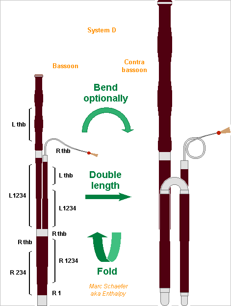
The bassoon's system applies nicely to the contrabassoon. With the left hand controlling the tenor and bass joint, the right one the boot, and few transmissions between all joints, the boot can be split in narrow and large joints and easily folded upwards. With all joints nearly as long, this makes a more compact fagotto. It's one folding more than the usual Heckel system contrabassoon, whose tenor joint begins at the bottom. The four first joints stay permanently together. The bell can be bent and run downwards like on the Heckel system for a smaller instrument. Or, as depicted, it can be straight and assembled to play: More compact transport case. Contrabass taller than the bass in the orchestra, ah. Resembles more a bassoon. Needs only wood knownledge from luthier and workshops, especially if all tone holes fit on the wood sections. I believe electrodeposition can make all bends and the bocal, if needed the bell, with little skills http://www.scienceforums.net/topic/111316-woodwind-materials/?do=findComment&comment=1031427 It can also make wide stiff tubes for the keys with reasonable weight. Per carbon filament winding or of possibly reinforced polyketone, all joint walls can be single parts. Marc Schaefer, aka Enthalpy
-
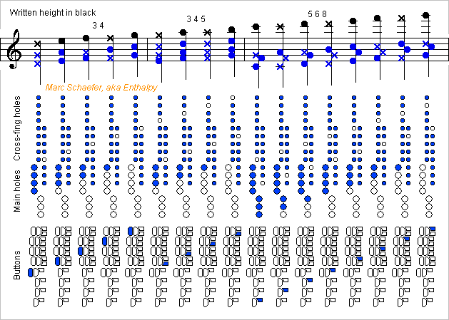
Because the soprito starts on the 2nd one and uses many higher modes, automatic cross-fingerings would be difficult. But here is a system to ease cross-fingerings for the soprito. Here 7 main holes achieve 8 notes, enough to join the modes, as these are high hence close to an other. The 7 main holes begin on C because an instrument's lowest notes tend to overblow abnormally, so the right thumb makes B and Bb. In the present system, a single front finger presses a key to move several main holes and define a note. The four upper main covers are closed at rest and the left fingers open one to four, while the three lower main covers are open at rest and the right fingers close one to three. The right index moves no main cover but can have a dummy button as sketched. The holes and the buttons are displayed separately on the sketches. Synchronisation hardware was suggested there http://www.scienceforums.net/topic/107427-woodwind-fingerings/?do=findComment&comment=999559 The musician presses only one button at a time as on a piano, excepted for the low B and Bb. This is easier than usual cross-fingerings. No alternate fingering nor trill key is foreseen. Extra buttons open one or two additional cross-fingering holes. Adjacent buttons can share the same cross-holes for different modes chosen purposely, so two sets of cross-holes suffice: Mode 1 isn't used by the Soprito. The narrow bore and the reed's size stabilize the mode 2. A register hole isn't excluded. Mode 3 reuses the same main holes as mode 3 with a register key. Mode 3 4 opens a cross-hole a fourth (5 semitones) higher than the highest open main hole. Mode 3 4 5 opens two cross-holes, a major third (4 semitones) and a major sixth (9 semitones) higher. Mode 6 isn't used. Mode 7 isn't used. Mode 5 6 8 opens two cross-holes, a fourth (5 semitones) and a minor sixth (8 semitones) higher. The system opens cross-holes 4, 5, 8 and 9 semitones higher than the highest open main hole, but adjacent main holes share cross-holes: a key for 4 and 5 is common to two adjacent main holes, a key for 8 and 9 too. The left index opens 4 main covers and 0 to 2 cross-covers. The right pinkie closes 3 main and may open 2 cross-covers. Narrow covers like at the oboe linder this drawback. The sketches show extra buttons that act on the main and cross-covers to help the musician. They need little extra local hardware. Without them, the musician would press simultaneously with the main cover 1 or 2 separate buttons linked directly with the cross-covers. Separate cross-covers ease the design of a well-tuned instrument. Register keys are not displayed. Probably at left thumb. One stabilizes mode 3, maybe an other suffices for modes 3 4 and 3 4 5, and still an other for mode 5 6 8. A sketch of the keys may come, perhaps. Marc Schaefer, aka Enthalpy
-
I have doubts now that the piccolo woodwind can have a single reed as depicted on Nov 06, 2017 http://www.scienceforums.net/topic/107427-woodwind-fingerings/?do=findComment&comment=1021947 because the reed's susceptance destimated as on Dec 03, 2017 http://www.scienceforums.net/topic/112039-woodwind-reed-susceptance/?do=findComment&comment=1026941 remains big even with an Ab clarinet reed. The clarinet's cylindrical bore is wide near the reed, whose susceptance shortens the air column reasonably. A saxophone (soprillo) is wide and plays the high notes only by the second mode, so hole positioning can correct the intonation. A single reed would shorten a narrow conical bore possibly too much, more than a quarter wavelength. Only a double reed, uncomfortably small, would fit. I may provide figures some day.
-
Bartók died over 70 years ago so all his compositions are in the public domain in Europe. This differs in the US, where property can last 100 years under some conditions.
-
The Norwegian government wants electric airliners for all flights under 90min in 2040 bbc.com and dailymail.co.uk In 2018, I see how to fly for 90min with batteries, but to divert to an airport 100nm away then wait 45min in the air, as safety demands, a plane doesn't resemble a profitable airliner. With liquid hydrogen and fuel cells, such a design is easy. The Atr42-72 modification I described on Apr 18, 2013 scienceforums.net does much more than that.
-
I haven't checked what notes composers specified. Could be a challenge, sure. Worse than a grand piano. Taking a symphonic orchestra on tour is already a headache. Not just the visas for 150 people. Most airlines ignore if one can take a violin in the cabin, but musicians don't want their instrument in the cold nor at low pressure, even less lost. And what about the materials? Violins use Pernambouc wood (Pau Brasil) and blackwood, both being prohibited to export or import in many countries. Woodwind use grenadilla and rosewood, same story. Then you have flutes of silver and gold not pure enough for France, whose law doesn't consider musical uses. Other funny laws may impose to fumigate all wood that enters a country as a protection against insects. Pssch pssch on the cello. Then you have the scores. Intellectual property differs among the countries, and a score acquired lawfully in Europe can bring you trouble in the US. I say: headache.
-
For infrasound, you may prefer a pressure sensor over a microphone. Possibly an array of sensors.
-

Sort of radiating beacon, long distance sensing ?
Enthalpy replied to Externet's topic in Engineering
Ultrasound scan can be directional. Some sonars are directional, especially for seabed mapping, and need a very wide base. Helicopter sonars are little directional because the size is few wavelengths, but submarines may have transducers over all their length. -
I know who would buy church bells: symphonic orchestras, simply. Presently they use tubular bells. All composers and conductors complain that their sound is weak, meager and sinister. Wagner for instance specified true bells but is often played on tubular bells, sometimes helped by a piano. Other orchestras try to develop plates and other shapes, which are less bad than the tubes but don't equal church bells. True bells, affordable and sounding good, would seduce the orchestras. Marc Schaefer, aka Enthalpy
-
Thanks JC! There are some common elements, but not the computation of a bandgap voltage by software. I'd not be surprised if someone had already done exactly what I propose. The idea is immediate enough.
-
Existing bassoons, both with French and Heckel systems, have extremely long tone holes, more so nearer to the reed. The common explanation, that the biassed long holes reached the proper positions at the air column when keys were expensive, is insufficient because presently we could have more keys and because these very inductive holes are a semitone to a tone higher at the air column than where pressure nodes should be. Instead, the bassoon needs the inductance and loss of the holes to soften the throat notes, more so due to the double reed and the huge first register. Also, musicians are used to the resulting illogic fingerings, especially at high registers. Anyway, these abnormal holes disturb the high register. If they are 60mm long (I don't have my bassoon here), that's lambda/4 for 1450Hz, the second harmonic of the conventional highest F#, so closed holes attenuate strongly the harmonics of the high notes and hamper the fundamental above the conventional G. Open holes don't act as a short-circuit neither, nor even as an inductor, but as an open-circuit near the lambda/4 condition. I'd like to get rid of these long holes if possible. Some notes do it already, for instance the C# at the end of the tenor joint. A new system is the opportunity since it changes the fingering anyway. I did not write "wide short holes at node positions" because this does not fit a double reed - and not even the clarinet and tárogató do it. But make the tone holes quite shorter than presently, and narrower to keep some of the inductance, the loss, or a bit of both (they are incompatible). I suppose that this array of holes makes the bassoon's 500Hz "formant" when not used in cross-fingerings. I want to give general explanations and figures some time. The oboe's chambers are an interesting option on the bassoon to soften the sound https://www.scienceforums.net/topic/113115-intentional-losses-in-wind-instruments/?do=findComment&comment=1035629 the absorbed band shall not be scaled to the bass instrument but still start at 3 to 4kHz to fit our perception https://www.scienceforums.net/topic/113243-sound-perception/?do=findComment&comment=1037471 and next which needs a small diameter ratio. Marc Schaefer, aka Enthalpy
-
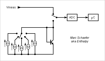
Hello everybody! Analog-to-Digital Converters (ADC) need an accurate voltage reference to convert an input voltage into a dimensionless number. The bandgap reference is common Wikipedia It uses the Vbe of two bipolar transistors used as diodes and passing different current densities. Vbe decreases with the temperature but the difference of both Vbe increases, and at least in simple models, a weighed sum of about 1.24V for silicon is independent of the temperature and relates with the bandgap. Excellent special chips do that. I propose here to let software make the weighed sum and more corrections for further improvements. I didn't check if this is already done. The same ADC converts the voltage to be measured and the Vbe. Software makes the comparisons and corrections. My circuit uses a single transistor at different currents successively. No more mismatch between to transistors. Accurate current ratios are still necessary. They can result from a number of identical resistors, measured and chosen if discrete, adjusted if integrated. Easier than matched transistors. Software can, better than a continous-time circuit, identify and correct error sources, especially the series resistance and the ideality factor, by using more than two currents. Several transistors in series can exploit the ADC range better. For instance the MAT-04 contains 4 and thrives to resemble ideal models. The ADC still needs an auxiliary voltage reference whose accuracy isn't critical but should be quiet enough. The Vbe should be measured often enough so software compensates the noise and drift of the auxiliary reference and removes most noise from the computed reference. This circuit adds the ADC's quantization noise several times, multiplied by 5 to 10 for the Vbe difference. Process many conversions, and use a high resolution converter, or improve it for Vbe with dither noise added there. Marc Schaefer, aka Enthalpy
-
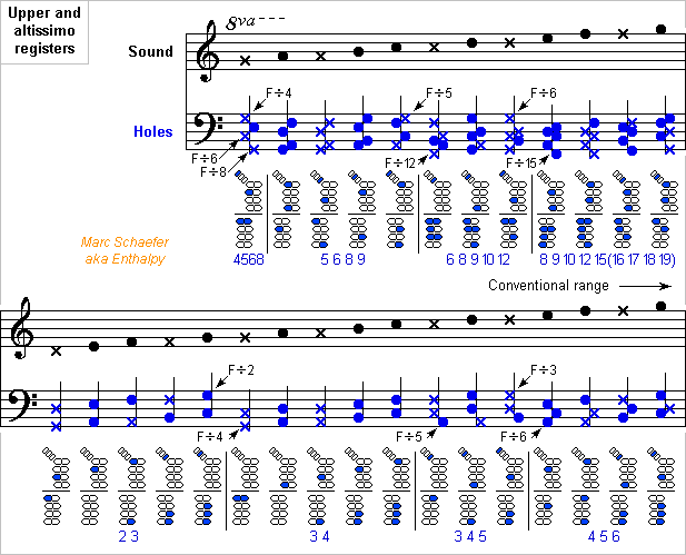
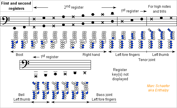
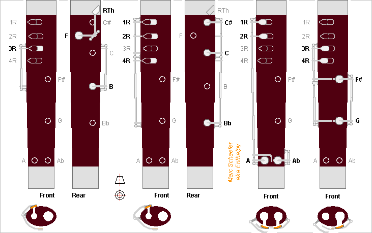
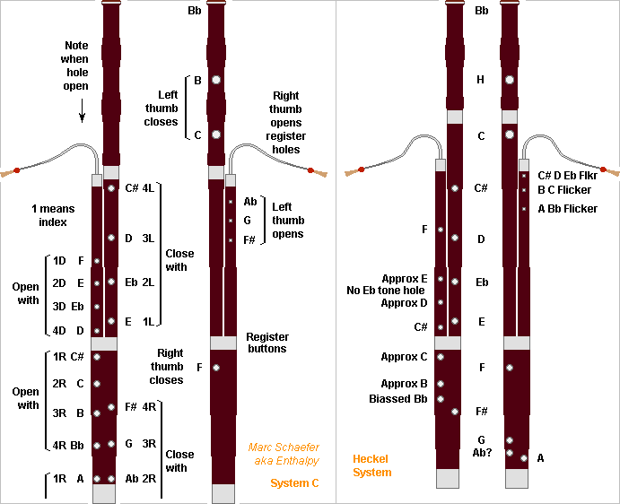
In the bassoon system I described here, the biggest difficulty for the musician in the first two registers is switching between them: open the left hand, press the register button, move the right fore fingers but open 4R and possibly 3R, all simultaneously. I tried to simulate it and found quite easier to press the register key when the right fore fingers move toward the wrist. The present system D does that: versus system C, it swaps the proximal and distal buttons at the boot. The tentative cross-fingering chart follows simple flute logic, so it's inaccurate for the bassoon; a design goal could be to let them sound all a semitone higher. The chart shows that the system provides flexible cross-fingerings that seem easier to play than on the Heckel system. Most bassoonists can play higher than the conventional G, so I added a chart for an altissimo octave but dropped the alternative fingerings. At C# and above, the fingerings get more complicated because I arbitrarily opened four holes above the main transition. At E and above, emission gets free help from many holes at the main transition, because this system opens them all and they are properly aligned as modes 15, 16, 17, 18, 19, 20 to reinforce the wave reflection. The other joints are kept from the system C and I swapped the fore buttons at the boot. Redundant views with few keys each make it legible. The sketches are not accurate to the pixel, and the holes' positions will evolve. An instrument designer would find shortcomings and improvements. At least, the simplicity is patent. Here too, the right thumb operates register keys at the tenor joint, so the right hand is high in this option. Maybe single tilted parts can connect the buttons to the Ab and G covers. The long keys for A and Ab holes should be wide for stiffness; electroformed tubes could be lighter, as suggested there http://www.scienceforums.net/topic/111316-woodwind-materials/?do=findComment&comment=1031256 Marc Schaefer, aka Enthalpy
-
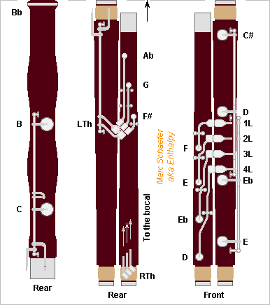
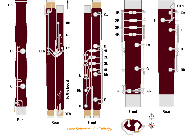
Here is a keyworks example for the bassoon with system C described on May 01 and 03, 2018 https://www.scienceforums.net/topic/107427-woodwind-fingerings/?do=findComment&comment=1050880 and outlined on Aug 18, 2018 https://www.scienceforums.net/topic/107427-woodwind-fingerings/?do=findComment&comment=1065554 Using preferably the button arrangement proposed on Jul 14, 2018 https://www.scienceforums.net/topic/107427-woodwind-fingerings/?do=findComment&comment=1060629 If someone develops this instrument, the positions of the holes will vary, the length of the joints possibly too, hence the design of the keys. Some tone holes are now at the rear, better than behind hands. Because my drawing capabilities were exceeded, I've changed again the positions of the proximal and distal buttons at the fore fingers: here the buttons that open higher tone holes are on the right, and the ones that close lower tone holes on the left, at both hands. In other words, the buttons are at the same side as the air column. Keys with long vertical shafts are not the usual choice at the bell. All buttons are spread comfortably. Small bassoonists will like that, older ones with arthristis too. Both hands are slightly higher than on the Heckel system, also nice to small musicians; that's mainly because I wanted the right thumb to operate register buttons hold at the tenor joint, but I ignore how useful they are nor how many there should be, and a transmission from the boot is possible too. The register keys must reach the bocal, but I didn't represent this on the sketch. The right side of the tenor joint is available. Register keys at the bocal are nothing new; I suggested shapes on May 13, 2018 https://www.scienceforums.net/topic/107427-woodwind-fingerings/?do=findComment&comment=1052574 This system makes keyworks much simpler than the Heckel system, and simpler than the French system too. It will be more silent too, as most keys consist of one button and one cover linked permanently. Marc Schaefer, aka Enthalpy
-
In the bassoon sketch of Aug 18, 2018, please read 1L 2L 3L 4L instead of 1D 2D 3D 4D.
-
Or rather, keep both joints as on the Jan 02, 2018 sketch, as well as the covers and fingers positions, but split the raise key for the left hand joint and add a transmission, so that the button and its articulation stays with the right hand joint at disassembly, and the rest of the key with the left hand joint. Marc Schaefer, aka Enthalpy
-
If you orient the magnets to repel an other, you get a force, and it's nearly the same as for the attractive orientation despite the induction is zero. So formulas based on B2S/µ are just b*llocks. More subtle computations based on volume integration as a function of the magnet separation are not manageable by hand and are heavy to program. Integrating over the current sheaths is faster to program and to run, and in some cases it even gives an algebraic solution. Clean comparison.
-
Hi JC, thanks for your interest! Electroplating alloys isn't trivial, I believe so! I've cautiously avoided to suggest anything about how to do that. I've only read that Cu-Ni is regularly done, Sn has a redox potential farther away from Cu than Ni has, but bronze can be electroplated too. Well, that's a job for specialized people and companies, like making seal rings or gears. I just love homopolar generators. Pity they are less fashionable presently, but maybe they'll come back. While low-voltage power electronics is tricky, every computer motherboard contains some, so designers must be less difficult to find than for a homopolar machine. Sure, inventions need luck to be adopted, improving over existing methods doesn't suffice. To my understanding, "church bell" designates a design of bells even if used by seculars, but about all big items must be in churches, and small ones have some efficient casting method. On boats maybe?
-
Power Mosfet were introduced historically (when I was young) with a channel length defined by a double diffusion instead of lithography which was too coarse at that time. They also offer a higher drain-source voltage. But low-voltage synchronous rectifiers don't need the huge Vds capability, and meanwhile lithography is much finer than necessary for transistors operating at 5V or 20V. So maybe a manufacturer could make power Mosfet with channel length defined by lithography, just like low-power Mosfets are made, but with a wider channel, low contact resistances and low thermal resistance? The symmetric transistors with an independent bulk connection would be nice in the above diagram, where one transistor would replace two of Rdson twice as low. Since pairs of Mosfet connected as above due to the parasitic diode appear from time to time at other circuits, maybe there is a market. For low power, the transistors exist already, but for a few amps, my quick search didn't find any. Marc Schaefer, aka Enthalpy
-
At the clarinet with even fingerings sketched on Jan 02, 2018 http://www.scienceforums.net/topic/107427-woodwind-fingerings/?do=findComment&comment=1031551 one raise button juts far out of the upper joint to be operated by the right thumb. The upper joint can be made longer and the lower shorter, so the holes operated by the right index are at the upper joint. Their covers may be articulated at the body's right side. Then both raise buttons stop about where the joints do and are less exposed. Alternately, one raise button can move the keys for the upper and lower joints, and the transmission be made at the border. It needs an adjustment. Marc Schaefer, aka Enthalpy
-
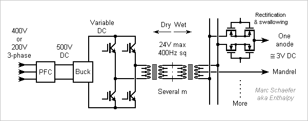
Considerations about the 3V*600A DC supply. Beyond, church bells, most apply to any electrochemical apparatus, and can be scaled up or down. The intermediate square wave at 24V*75A can travel cheaply over 5m or 10m while 600A conductors are uneasy to move. The conversion from three-phase mains is in a separated room, clean and dry, prefiribly a floor higher than the bath (as opposed to the nuclear power plant in Fessenheim). A 24V shock has the (legal) reputation to be survivable even in a wet environment, more so at 400Hz. The waveform should be smoothened. 400Hz makes a reasonable transformer to 3.2V: with 50µm Fe-Si tape, the core can have the double AMCC-500 size and weigh 6kg, while each 3.2V winding has two turns of 3mm thick Cu foil and the primary thinner foil. Losses are around 45W. A nanocrystalline core of AMCC-250 size and single-turn secondaries would reduce the losses to 20W, which electricity saved over few hundred bells may pay. Iron powder or ferrite cores would reduce the transformer with frequencies over 20kHz but are fragile, and switching components would waste more power. Multiple 3.2V transformers would save cable volume if the 3.2V current returns over a shorter path. For a church bell, it means contacts inside the mandrel near the rim, and transformers nearby. This might get interesting at bigger bells. Contacts distributed on the fresh deposited surface are more difficult: they should move regularly for even deposition, and make sense with immersed transformers. MOS rectifiers waste far less voltage than diodes, they can swallow pulses to tune the deposition rate locally, and also reverse the DC voltage, all by individual gate control. Possible upgrade for apparatus still using diodes. Unless some manufacturer avoids it, the parasitic diode demands MOS pairs. The dual secondary transformer saves MOS and losses. For 3.2V output, the gate control can be referenced to the mandrel potential. Some deposition processes apply periodically a short and strong reverse current to even and smoothen the deposited layer. The sketched circuit achieves that; I'd limit the intermediate voltage to 24V even during the reversed current, hence use a smaller voltage for the normal polarisation, and increase the frequency during the increased voltage periods. Marc Schaefer, aka Enthalpy
-
Here's a possible aspect of a bassoon with the system C described on May 01 and 03, 2018 with two buttons per fore finger https://www.scienceforums.net/topic/107427-woodwind-fingerings/?do=findComment&comment=1050880 The tone hole positions are approximative. Up to A they're deduced from the low holes, from Bb to C# they drift progressively up to a semitone higher as they get narrower. I'd not make the holes as long as on the French and Heckel systems since this must hamper the highest notes: just shorter and a bit narrower to keep the losses. The hole positions I indicate at the bore for the Heckel system are eye estimates. As my system opens all holes below the main transition, the holes are regularly spaced, and the intonation and emission hopefully even. Few transmissions are needed. The left fore fingers open holes at the tenor joint and close others at the bass joint, each joint carrying only its own keys. The right fore fingers open and close holes at the butt only. The left thumb opens one of three tone holes whose keys reside fully on the tenor joint, as inspired by Heckel's overblowing keys, or closes one or two tone holes at the bell, needing transmissions from the bass joint. The right thumb closes locally a tone hole or opens one of several register holes at the bocal whose buttons may reside at the tenor joint, needing transmissions. My system frees early the right thumb, which can operate several register keys high on the bocal, to make high notes hopefully easier, stronger, and with nicer sound. I could keep the bassoon's nice shape, size and aspect. The boot is little longer to turn between A and Ab, whose holes may be slightly biassed to the bottom. Turning between Ab and G is an alternative. The C# hole is at the boot, but the hole and key could be at the tenor wing and the right index still move it. The F hole and key could also be at the bass wing if accessible to the right thumb. The tenor joint doesn't go as high, the bocal length and shape compensate that. Or give the left thumb a fourth tone hole there, if it provides an advantage unseen by my tentative fingering charts. I've drawn the C hole at the bell so all parts are equally long for a smaller case. Though, manufacturers use to prefer a longer bass joint and save a transmission. The keyworks seem much simpler than on existing bassoons. I may give sketches some day. The key arrangement I proposed is thought for this bassoon first: https://www.scienceforums.net/topic/107427-woodwind-fingerings/?do=findComment&comment=1060629 Fingerings look easier for the two first registers, and cross-fingerings for the higher registers may be easier and should be more efficient. If the sound and emission are more even too, my system would be an improvement. But it needs a lengthy development due to the double reed imposing narrow tone holes. Marc Schaefer, aka Enthalpy
-
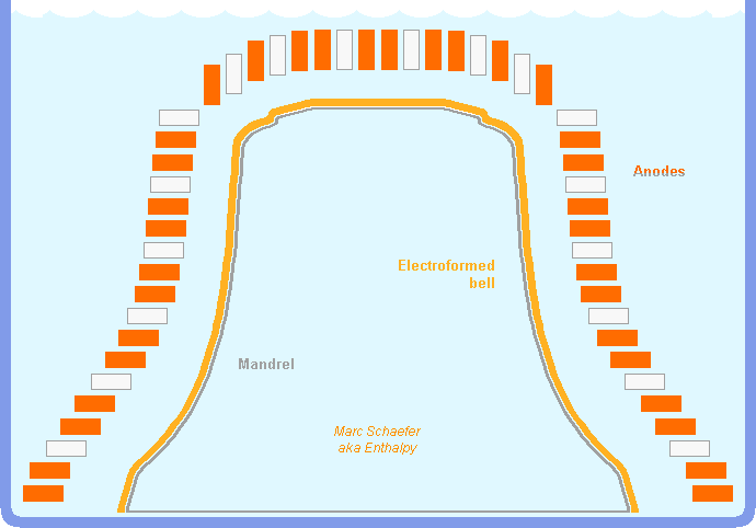
Hello dear music lovers! Church bells are still made today like in the Middle Age: Cu80Sn20Pb0 bronze cast in a one-way clay mould. One batch of varied middle-sized bells takes six weeks of hard work to ten persons. I propose instead to electroform them. A well-developed technology, electroforming can deposit varied metals and alloys, from ultra-thin to thick, on diversely shaped mandrels, bulk conductive or not, and separate the created item from the mandrel. Here bronze and the bell shape are easy. Maybe the mandrel can be of wax on wood, or talcum-loaded paraffin... In one interesting option, the mandrel itself would be obtained by electroforming on the inner face of a good existing bell. For the parting film, ask a specialist. The current density varies with the rest, let's take 500A/m2 as an example. This grows 11mm/week copper and slightly more bronze, faster than traditional mould making. The current in copper and tin electrodes, and initially the electrolyte composition, control the alloy composition; I ignore if the electrodes can be bronze. A D=0.8m bell has around 1.2m2 surface, needing 600A (or less since some parts are thinner) and roughly 3V and 1.8kW only. The anodes are closer to the created item than depicted, their shape and number is not representative. Maximum 30mm thickness take 3 weeks, mean 25mm just 700kWh costing 150€. Upsizing is easy. Schottky diodes could provide the DC current, but I prefer MOS to reduce the losses and regulate the current, for instance by pulse swallowing. Electronics can produce a square single phase around 24V (safer than 500V) distributed to local transformers, at 400Hz for laminated iron cores or higher for iron powder or ferrite. Some processor can distribute the swallowed pulses smartly. The currents must be monitored automatically, the thickness could be measured manually from time to time but is better monitored automatically too. The bath needs limited cooling. Rotating the electrodes (or the bell) during the growth may achieve a rounder shape. Then, the transformers better rotate with the electrodes, so fewer contacts pass less current. I've no opinion about the internal stress of electrodeposited bell bronze nor its acoustic qualities. It can be heat-treated afterwards. Titanium parts are isostatically hot-pressed (in silicone) after casting, this may apply here too. Impurities from the mandrel or parting agent must be removed from the bell. Marc Schaefer, aka Enthalpy


