-
Posts
3887 -
Joined
-
Last visited
-
Days Won
1
Content Type
Profiles
Forums
Events
Everything posted by Enthalpy
-
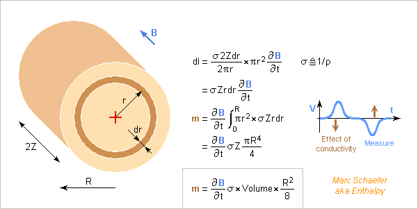
What is the consequence of a conductive sample on a measure? The drawing computes it for a cylindrical sample, but shape details matter little. The excitation induction is supposed essentially unaffected by the material since the main measured effect is about 10-5. The magnetic moment due to conductivity results from the excitation induction and must be smaller than the susceptibility effect. To achieve 0.01* the previous 2.4µA*m2 from 0.3T/3ms in 1cm2*1cm sample, the material must conduct less than 60S/m = 16mohm*m or 600mS/cm in the unit of the table: Electrical Conductivity of Aqueous Solutions, in recent CRC Handbook of Chemistry and Physics this allows all electrolytes listed there. Metals conduct much more, up to 106* the previous limit, but can still be measured if the sample consists of insulated bands, wires or coarse powder grains up to 103* smaller as needed: D=10µm. Maybe native or grown oxide suffices to insulate the grains, but I'd trust instead a suspension in a liquid or some solid wax. Apply a law of mixtures. Marc Schaefer, aka Enthalpy
-
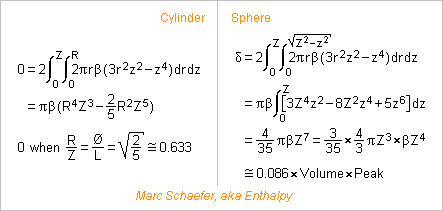
Some materials, mainly man-made ones like polymers and technical ceramics, have homogeneous susceptibility and can be machined to accurate shape. Then, as the deviations of the induction have opposite signs along the axis and the radius, special proportions of the sample can let the deviations compensate an other. The measure is more accurate, and the sample can be bigger. Using the radial gradient of the induction obtained on 08/04/18, the image computes the compensation condition as Z/R=D/L=sqrt(2/5)~0.633 for a cylinder, within a domain where the on-axis deviation is written as -beta*z4, and the residue for a sphere of radius Z. The sphere isn't bad, provided it's accurately shaped and homogeneous: it compensates by 0.086, or to 0.086% if beta*Z4=1%. For every shape, an accurate position is necessary. A cylindrical or spherical container filled with a liquid or even a powder could keep the good properties if the filling is complete and uniform. Marc Schaefer, aka Enthalpy
-
On 07/29/18 02:14 PM, I meant "the sample rotates at 2.5Hz", not 5Hz. 5Hz is possible too. The duration and distance of the integration windows can still be multiples of 20ms or 16.67ms, and the signal-to-noise improves by 3dB for each pulse pair and by 6dB if averaging over an identical duration.
-
Mass estimates for the 2015 BZ509 mission to bring samples back. An Atlas V 551, Ariane V, Ariane 64, H-IIB puts 18800kg on a naturally inclined 400km low-Earth orbit. The payload volume demands a bigger fairing, or an own stage, or the whole mass could be reduced. According to the escape script of Jul 27, 2014 http://www.scienceforums.net/topic/76627-solar-thermal-rocket/?do=findComment&comment=818683 Eight D=4.57m sunheat engines bring 14503kg to 127Mm apogee with adequate tilt in about 17 months. Or add engines, 30 kg each. A small O2+H2 engine gives 4233m/s over Earth's gravity and speed to 11450kg. If accounting tank masses, the mass optimum would be over 4233m/s, and exceeding this new optimum would save volume. 890kg of O2 and shared H2 tanks and 301kg engine are dropped, leaving 10259kg. A 25kN engine with fuel cells and electric pumps would outperform the RL-10. The eight sunheat engines bring 5042kg to 13058m/s over Earth's gravity and speed in 33 days. The tank for 5.2t H2 is dropped, leaving 4108kg heading to Saturn in 2.3 years. The optional own stage can stop here or already after escape. I take 182kg per ton of H2 for insulated balloon tanks in trusses that carry a heavy load during launch. Dropping the trusses earlier, for instance with the O2+H2 engine, is uneasy but would save mass. Here I neglect the 2.5° inclination of Saturn's orbit, but it could cost up to 1.8km/s. The Saturn flyby is for free. Hohmann transit to BZ509 at 3.18AU perihelion takes lengthy 8.6 years. Tilting from 180° to 163° takes approximately 3856m/s. Eight sunheat engines optimized for about 6.7AU need 1.2 year to eject 1345kg. The chambers may differ from the ones used at 1AU, which adds few unaccounted kg, but then 100kg of 1AU chambers would have been dropped before. Four 30kg engines and 245kg tank are dropped, leaving 3332kg heading to BZ509. Four engines brake by 1331m/s in 190 days because dice limit the sunlight to the power available at 6.7AU. A shorter trip would need more fuel mainly here. 2993kg arrive at 2015 BZ509 full of nice tools and toys. I take Saturn at aphelion, BZ509 at perihelion when arriving and at aphelion when leaving. Lengthy orbits don't let choose, and I didn't check the consequences of BZ509 being far from its nodal points. ========== Of the 2993kg, 300kg are a return capsule, 100kg a bus for the return leg, 100kg are four sunheat engines kept for the return, 110kg the tank with 236kg H2 for the return and 339kg already used upon arrival. The other 2147kg comprise 400kg of bus and 1747kg to split among remote sensing and landers. Some robotics catch the landers and transfer the samples. As I suggested elsewhere, remote sensing could include a pulsed laser powered by the sunlight concentrators, hydrogen and xenon jets to erode the surface, a hydrogen gun for deeper sensing, maybe tethered hollow harpoons to take samples without landing. I'd prefer several landers of different construction for redundancy: landing, anchoring and sampling hardware... The size, shape, mass and composition of BZ509 are unknown. Reflection suggests D=2km, then iron-nickel would weigh 3*1013kg. Take-off would need 2.2m/s provided by springs, possibly hydraulic, and the ferry might orbit below R=3.5km but its sunheat engines couldn't levitate it. But if BZ509's mean density is 500kg/m3, the Lagrange point is at R=0.9km, so no orbit is possible. As with Chury, staying near BZ509 is difficult, until someone has an idea. Between the nodal points, the mission has 5.8 years to take probes, optionally more for remote sensing. ========== 858kg leave BZ509's vicinity. The four sunheat engines use 236kg in 148 days at 7.09AU to brake by 4000m/s within the retrograde orbital plane to join Earth directly. If I misunderstood and detilting by 17° is needed, the sunheat engines still achieve it, but the capsule must be half as heavy and the leaving aggregate twice as heavy. Not the hypothesis here. Not forgetting the fuel for fine-tune would be better. The bus, engines and tank separate from the 300kg capsule that re-enters Earth's atmosphere at 68km/s. A capsule has to decelerate by ~500g or it would exit the atmosphere, ouch. Some flat form for L/D=1, if feasible for that speed, would reduce it to 74g downwards and backwards, or total 105g. The 300kg capsule comprises: 146kg heat shield 24kg parachute 80kg bus 10kg sample boxes, as there http://www.scienceforums.net/topic/85103-mission-to-bring-back-moon-samples/?do=findComment&comment=823276 40kg samples of extrasolar matter for the Earthlings' labs. Marc Schaefer, aka Enthalpy
-
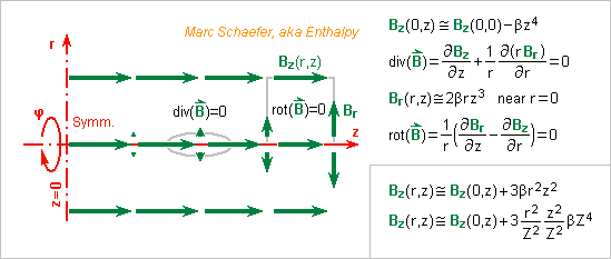
Most sources show that the Helmholtz coil provides an induction uniform along the z axis because this is simple algebra. But how uniform is the induction radially? A less simple algebraic solution must exist off-axis, possibly with Bessel functions. Here I prefer to show more generally that, due to its properties in vacuum, if the induction is uniform along the symmetry axis, it's uniform radially too, and the deviation can be estimated. With approximation signs on the sketch, but a mathematician would do it cleanly with Taylor series and Cauchy remainder.. Here the on-axis induction Bz(0,z) is maximally flat, varying as beta*z4 approximately. div(B)=0 links the axial variation of Bz with the radial component Br near the axis, which is small, and if beta=0 it's zero. curl(B) aka rot(B)=0 links the axial variation of Br with the axial component Bz near the axis, which varies slowly with r, and if beta=0 it's uniform. So how wide can a sample be? Let's take a sphere centred on r=z=0 with radius Z. The radial variation is like r2z2 but on the sphere r2+z2=Z2, so the radial variation is maximum for r2=z2=Z2/2, or +0.75*beta*Z4, while the axial variation is -0.25*beta*Z4 there and -1.00*beta*Z4 at z=Z. That is, the sphere is a reasonable boundary. With the previous 2Z=1cm it provides 0.5cm3 to the sample. I've deduced function values on a surface or volume from the values on a line. That's common with a differential equation as we have here, and may even be accurate far from the line. We could have written Bz(0,z) with more powers of z, or as a Fourier series... I suppose a link with holomorph functions. In a vacuum domain not surrounding a current, div(B)=rot(B)=0 lets define a scalar potential grad(psi)=B with delta(psi)=0. Within a phi=const plane, delta(psi)=0 makes psi the real part of a holomorph function, so knowing its values on a line fully defines it on the domain. Marc Schaefer, aka Enthalpy
-
I shouldn't have, because if now I compute the vector product properly using the sine and not the cosine, I get a signal twice as big that equals the other computation on 07/22/18 03:11 PM. But this doesn't reject interferences. If P*Q measures are averaged, they should start at P different angles from the start of a mains' period, the angles being equally spread over a turn. Examples: 2Q measures can start at 10° and 190° from the start of a mains' period. 3Q at 20°, 140°, 260°. 6Q at 1°, 31°, 61°, 91°, 121°, 151°. This squashes the interferences at the mains' frequency and its harmonics not multiple of P (it's a sum of the roots of 1 in the complex plane) so a big P has some usefulness. Exact angles improve the rejection, so the measures should start when the sample's speed is stable, and even at big P*Q, precise timing improves over sampling asynchronous with the mains. Marc Schaefer, aka Enthalpy Sound science. As the title says, and using the most obvious method. Apparently it hasn't been developed up to now, I don't know why.
-
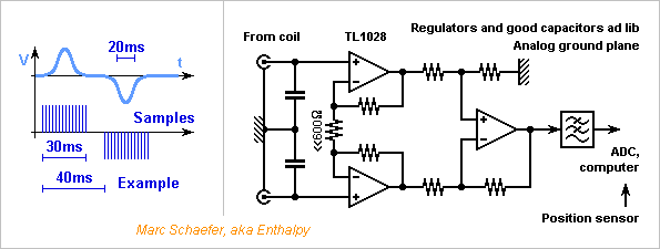
Signal, noise, electronics. If the sample rotates at 5Hz on R=0.1m, the enter and exit voltage bumps can be 20ms wide and spaced by 40ms, while 30ms or more are needed to integrate them completely. Helmholtz' region of uniform induction provides a time of zero voltage between the bumps where integration can stop and start. Software can integrate each bump over 30ms and compute the difference. Integration times and their distance are usefully multiples of 20ms to reject interferences at 50Hz, or 16.67ms at 60Hz, and the repetition period an odd multiple. As the sample's rotation or oscillation frequency can vary, a separate sensor can tell the instantaneous position and software determine the best start and duration of the integration windows. With the example times, the integration picks noise from 10Hz to 40Hz, with complicated limits. The window can be smoothened a bit, but we make metrology here. A few TL1028 make a good differential amplifier (instrumentation amplifiers are about as good: AD8229, AD8428, AD8429 and competitors) http://www.analog.com/media/en/technical-documentation/data-sheets/1028fd.pdf Noise per input is 1nV/sqrt(Hz) and 3pA/sqrt(Hz) at these frequencies. Each half-coil is essentially resistive: 340ohm and at 40Hz j200ohm. After integration and enter-exit difference, the differential noise is 24nV. Two 2000 turn coils pick 44nV*s from a 1cm3 chi=10-5 sample, or mean 1.5µV over 30ms. The enter-exit difference is 2.9µV or 100* the noise voltage. A resolution of chi=0.01*10-5 results from averaging few measures. The sample can be smaller. The analog circuit shall provide limited and fixed low-pass filtering. This leaves the mean value of a bump untouched, provided that the time of zero voltage between the bumps is kept. At identical transition and selectivity, inverse Chebychev and elliptic filters have a faster and quieter time response than Chebychev and Butterworth, don't believe books. The considered amplifiers have an offset smaller than a strong signal. The analog circuit can pass the DC to avoid measurement errors and to settle quickly despite the slow signals. Enter-exit bumps difference by software removes the DC and low frequency components. A PC distributes irregular >10A in unshielded cables and its processor draws >100A. It's a bad source of magnetic and conducted interferences. If box and distance don't suffice, consider a microcontroller instead. Marc Schaefer, aka Enthalpy
-
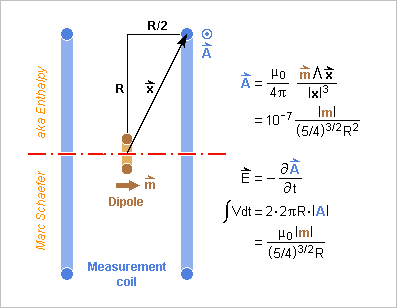
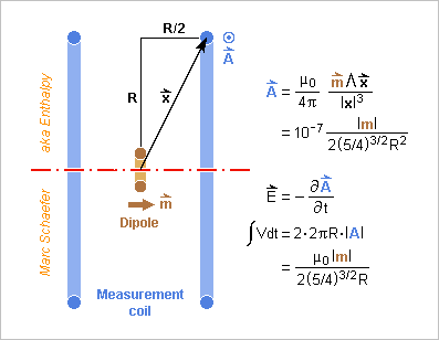
"One can integrate over the measurement coils the vector potential A created by a small magnetic dipole" to compute the signal induced by the sample, but on 07/22/18 03:11 PM I took an other route. Here is the standard one, with most computations in the drawing. The A potential by a magnetic dipole has a know algebraic expression computed from Biot and Savart https://de.wikipedia.org/wiki/Biot-Savart-Gesetz https://en.wikipedia.org/wiki/Magnetic_dipole If I inject the former m=2.4µA*m2 and R=50mm I get 22pV*s per turn in the coil pair, precisely half as much as previously. I trust today's computation. The former had possibly a logic flaw because of the two coils. The setup has much noise margin anyway. Marc Schaefer, aka Enthalpy
-
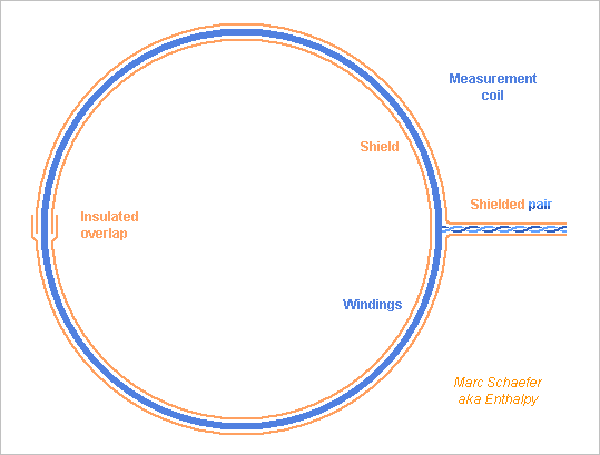
It is well known, but not by everybody, so here's a sketch of an electrostatically shielded coil. A closed loop would allow current induced in the shield to reduce the voltage induced in the windings, so the shield is interrupted. At such low frequencies, the ends of the shield can overlap if something prevents an electric contact, and the shield needs not be symmetric around the feed point. Nor is a symmetric cable vital here. ========== I have forgotten "=0" in the conditions of a maximally flat induction at a Helmholtz coil.
-
You believe what you want. I don't need any more to experiment and learn on this topic. Hint: B2S/µ or 0.5 B2S/µ might have been correct if B didn't depend on the gap between the magnets. This isn't the case with permanent magnets. My suggestion is that you measure magnet forces or search for manufacturer's data and check how wrong such formulas are.
-
The company that produces the magnets sometimes gives a pull force in the data sheets. If not, it gets complicated: no algebraic solution. If the magnets are long and narrow, I've derived an algebraic solution that fits manufacturer's data rather well, there https://www.scienceforums.net/topic/59338-flywheels-store-electricity-cheap-enough/?do=findComment&comment=876426 Do not trust formulas like B2S/µ, they are wrong.
-
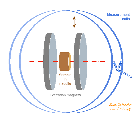
Some crystals are anisotropic and their susceptibility is a tensor. By orientation of the measurement coils, my apparatus measures the nondiagonal terms of the susceptibility. Here a continuous rotation can't insert the sample in the measurement volume and extract it. A mechanical oscillation seems better, with enough amplitude to go over the centre or even exit the measurement volume in both directions, and can serve with the previous orientation too. The oscillatory pumps over oil wells may give inspiration. A spring can let exceed 1g if desireable. The sample's orientation is paramount, so parallel wires as sketched don't suffice: it needs at least a truss. Marc Schaefer, aka Enthalpy
-
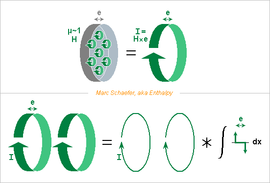
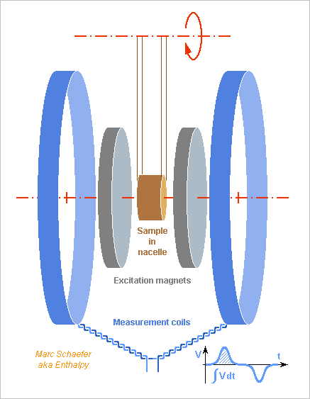
On the previous sketch, permanent magnets create the excitation field without iron. Rare-earth and ferrite magnets have a small permeability, like 1.05, which I neglect. They are equivalent to a current sheath I = e*H flowing at their rim. This lets arrange them as Helmholtz coils https://en.wikipedia.org/wiki/Helmholtz_coil 10mm thick Nd-Fe-B magnets with H=1MA/m are as strong as 10kA*turn, or 100A in 100 turns, wow. With D=60mm, the maximally flat induction distribution would result from 30mm spacing between the magnets if they were thin. This creates B=0.30T at the centre, dropping by 1% at +-5mm axial distance and a similar radial one. A tiny induction dip at the centre would slightly widen the good volume, but the maximally flat condition is algebraically simple: dB/dx = d2B/dx2 = d3B/dx3 where the odd derivatives vanish by symmetry and the second by adjustment. The magnets' thickness e spreads the equivalent current by the amount e. It's equivalent to a convolution of the current distribution by a square function of length e, and this square function is the integral of two opposed Dirac spaced by e. The convolution at the created induction incorporates some d2B/dx2 from x around the centre. For reasonable e, this can be compensated by increasing a bit the spacing. I expect an algebraic solution by this Diracs convolution method, writing d2B/dx2 with the degree change due to the integral, and solving for the maximally flat condition. I didn't check if this method is new, and don't plan to detail it. It applies to coils too. Permanent magnets are strong but dangerous. Electromagnets could replace them, with cores to achieve an interesting induction. The cores must allow easy flux variations. A uniform induction would result from FEM optimization and CNC machining of the poles. The measurement coils can surround the exciting coils; I'd keep them distinct to reduce noises. ========== The measurement coils too are arranged according to ol' Hermann. A sine current flowing in them would create a uniform induction in the measurement volume, hence induce a voltage in a small loop independent of the position there. Because the mutual induction is the same from object A to B and B to A, the same sine current in the small loop would induce the same voltage in the measurement coils from all positions in the measurement volume. This way, all points of the sample within this volume contribute equally to the measurement signal. To compute the signal induced by the sample, of which all points are equivalent, one can integrate over the measurement coils the vector potential A created by a small magnetic dipole, which has an algebraic expression. Instead, I compute here the mutual induction from the measurement coils in the sample. 1A*t in each R=50mm coil create 18µT so a 1cm2*1cm sample receives 1.8nWb and the mutual induction is 1.8nH, from the sample to the measurement coils too. If the 1cm2*1cm sample has a susceptibility chi=10-5 in 0.30T, it's equivalent to a dipole of 24mA and 2.4µA*2 that induces 43pV*s per turn in the coil pair, for instance 14nV over 3ms transitions of the sample in and out the excitation field. ========== If each coil has 2000 turns, the signal is 86nV*s or 29µV over 3ms. D=0.29mm enameled copper make 340 ohm resistance and about as much reactance at 40Hz. Integrated over 40Hz and with 2dB noise by the differential amplifier, the thermal background is 19nV, so the measure can be accurate even for smaller samples. Good amplifiers can cope with a smaller source resistance, that is, fewer turns. The measurement coils (and their feed cables) demand shielding against slow electric fields, especially at 50Hz and 60Hz. A nonmagnetic metal sleeve can surround each coil if the torus it makes is not closed, but its ends can overlap if insulated. It's better symmetric starting from the feed cable and connected to the feeder's shield. The situation is much easier than for electrocardiograms. 100mA*2mm*0.5m at 1m distance and 50Hz induce 0.2µV in the coil pair, so a decently calm environment needs no magnetic shielding. Averaging successive measures would further filter out interferences by the mains. The sample's cycle can be desynchronized from the mains or have a smart frequency ratio with it. ========== An electric motor can rotate the sample if it's shielded by construction or is far enough. An adjustable counterweight is useful. Or let the sample oscillate as a pendulum. The nacelle, or bottle for liquids and powders, should contribute little signal. Thin construction of polymer fibres is one logical choice. Its contribution can be measured separately and subtracted by computation. The parts holding the magnets and coils must be strong and also stiff. A 2000 turns coil moving by 1nm versus the magnet gets roughly 100nV*s, as big as the signal, so this shall not happen at the measurement timescale. Not very difficult, but needs computational attention. The nacelle's movements must be isolated from the magnets and coils. ========== If a sample keeps a permanent magnetization, it should be measured without the excitation magnets. Metals conduct too much, but most electrolytes fit. Marc Schaefer, aka Enthalpy
-
Hello everybody! Because it is small, like 10-5, measuring the para- or diamagnetic susceptibility (chi = µr-1) of materials is uneasy. Overview of Methods for Magnetic Susceptibility Measurement P. Marcon and K. Ostanina describes several setups. The Gouy balance and the Evans balance measure a force, often for liquids https://en.wikipedia.org/wiki/Gouy_balance https://en.wikipedia.org/wiki/Evans_balance http://www.iiserkol.ac.in/~ph324/ExptManuals/quincke%27s%20manual.pdf An other method uses a Squid, which is sensitive and differential by nature, but demands cold. The less expected setup measures the tiny change of coil (or transformer) inductance due to the material, with an identical but unloaded coil for differential measurement. I propose instead to use a constant excitation magnetic field immobile versus the measurement coil and to move the sample in and out the sensitive volume. Then the induced voltage results only from susceptibility of the sample and nacelle. The electronics can easily integrate the voltage over time to obtain the flux variation in the measurement coils. Adequate arrangement of magnets and measurement coils, for instance as by Helmholtz, define a measurement volume where both the excitation field and the measurement sensitivity are uniform. In the sketch, permanent magnets make the excitation field, and a rotation passes the sample in and out the sensitive volume. Other possibilities exist. Figures should follow. Marc Schaefer, aka Enthalpy
-

Neanderthals Built a Water Reservoir
Enthalpy replied to Enthalpy's topic in Evolution, Morphology and Exobiology
And if I pay more attention to the text accompanying the research paper's images (I don't have the full paper), then I write fewer pointless comments... Erratum and comments to my message of July 15, 2018 6:40 pm... The paper does not tell that calcite doubles its susceptibility upon heating. It's clay. A clay sample from that location more than doubled its susceptibility "upon heating". Doubling can't explain the measured magnetic anomalies. Maybe the temperature was too low: Kostadinova-Avramova and Kovacheva observed a much stronger effect at 700°C than 400°C. The effect results from permanent magnetization much more than from increased susceptibility. The same clay sample can be re-heated to 700°C for new measures. The irregular black colour, especially on fig.3, resembles char by a fire, and spectroscopic analysis confirmed. The authors carefully dated several fires to an age compatible with the artefact itself, that is, with a few thousand years accuracy. A previous study by C-14 had found a fire much more recent. Dating by the growth rings at calcite has already been used. I would find hard to believe that the orange or brown colour results from fire: too uniform. Clay incorporated to calcite looks better to my (untrained!) eyes. The more recent stalagmite on the artefact is white. Chemical analysis would tell better if the orange calcite incorporates clay. Comparison with other near locations in that cave would indicate whether that colour was brought by a flood, by temporary changes in the stalagmite formation, or by human action. I haven't seen whether the orange colour reaches deep in the stalagmites or is superficial. Clay samples from hearth and from nearby locations in the cave would usefully have a known orientation, to compare their magnetization with the observed perturbation, before and after new heating. -

Neanderthals Built a Water Reservoir
Enthalpy replied to Enthalpy's topic in Evolution, Morphology and Exobiology
Sure. Failed designs show much bigger examples at Olkiluoto, Flamanville, Tianshan and next Hinckley Point. What I like less at explanations by failed attempts is that they offer so many variants that they can explain anything. Or if you prefer, they are not refutable. It does not mean that they are wrong, only that reasoning on them is virtually impossible. This is a seducing interpretation, but it has some difficulties. Why go so deep in the cave? 50m would suffice, they walked 300m from the entrance in a difficult terrain. That's dangerous and lengthy. For a safe water supply available only there, I'd do it. To sleep comfortably, I'd prefer a nearer location. The artefact is (at least today) in a location low and inundated. That's where I would not put my camp. The "walls" follow contours of constant altitude. Perfectly justified for a reservoir, while a camp wall would have straight walls where the terrain drops. Traces interpreted as fire remnants are everywhere, including on the "walls", rather than at the centre. Their skull volume exceeded our. But so does elephants' skull too. The surprise to archaeologists is that they had seen no construction by Neanderthals prior to this one. And what is intelligence? Intelligence is specialized. My cat was intelligent to interact with humans and exploit us, but he never made something with an object, except if the object represented a prey. He wouldn't even carry an obstacle away from his bed. Bruniquel is the first time archaeologists find indications of Neanderthals going deep in caves. 175,000 BP was during a cold period, yes https://en.wikipedia.org/wiki/Ice_age Good point, the problem of wood transport. =========================================================================== The human bones in Jebel Irhoud, presently attributed to Sapiens Sapiens, were dated to 300 000 BP in 2017, that is, after the paper about the artefact in Bruniquel. https://fr.wikipedia.org/wiki/Djebel_Irhoud https://en.wikipedia.org/wiki/Jebel_Irhoud This half-opens the alternative possibility that Sapiens Sapiens made the artefact in 175 000 BP in Bruniquel. No evidence exists of Sapiens Sapiens in Europe at that time. From now-Morocco to now-France, humans would have needed to cross the Gibraltar straights (deep water during the ice age too). But few years ago, archaeologists saw only Neanderthals in Morocco at that time. They may change their mind for Europe too. So what's more difficult to accept: first evidence of Neanderthalensis making artefacts deep in caves, or first indication of Sapiens Sapiens in Europe at that time? Please take with mistrust, as here I'm very far away from anything I imagine to understand. -

Neanderthals Built a Water Reservoir
Enthalpy replied to Enthalpy's topic in Evolution, Morphology and Exobiology
At Bruniquel cave's artefact, the paper's authors recorded a strong magnetic gradient that excludes many origins. The data is mapped on fig. 5 with explanations http://www.nature.com/nature/journal/vaop/ncurrent/fig_tab/nature18291_SF5.html (it was there) they saw +-12nT/m at several places, up to +-24nT/m. I didn't see the measurement altitude and suppose it was 1m over the flat bottom, maybe 0.5m over the construction's peaks. The apparatus takes the difference between two Geometrics G858 sensors http://www.geometrics.com/geometrics-products/geometrics-magnetometers/g-858-magmapper/ which measure the total induction by caesium vapour cells and are stacked vertically with 0.22m separation, so "gradient" means the vertical gradient of the total induction. ---------- I compare with what a small magnetic dipole achieves: the strongest case is the polar component in the polar direction, B = 2*10-7mR-3 where m is the magnetic moment in A*m2, B in Tesla, R in m http://www.phys.ufl.edu/~acosta/phy2061/lectures/MagneticDipoles.pdf https://en.wikipedia.org/wiki/Magnetic_dipole grad(B) = 6*10-7mR-4 (put signs as you like) 24nT/m would need 2.5mA*m2 at 0.5m or 40mA*m2 at 1m - or half as much for 12nT/m. We can already note that today's best permanent magnets of FeNdB provide 1100kA/m, so at 1m such a supermagnet would need to be 2mm3 big. ---------- The magnetic susceptibility X of the artefact's materials deform the geomagnetic field, but how much of which materials does it take? At Bruniquel, the total geomagnetic induction is 46µT, tilted 58° from the horizontal https://upload.wikimedia.org/wikipedia/commons/f/f6/World_Magnetic_Field_2015.pdf https://en.wikipedia.org/wiki/File:World_Magnetic_Inclination_2015.pdf and the total geomagnetic field 37A/m. I take everywhere SI conventions, where X is dimensionless and 1+X is the relative permeability µr: Induction B (T) = (1+X)µ0H (H field in A/m) with µ0=4pi*10-7 by SI definition A volume L*S of material with susceptibility X lets pass the same induction as vacuum if we add a current H*X*L around it and then the external distribution is the same as for vacuum. This current has a moment H*X*L*S proportional to the item's volume. And since the added current compensates the item's presence, the item has the same external effect as the added current without the item. Yes, this can be done better. An algebraic solution exists for a sphere, and by packing spheres of varied radii, we can fill any shape. Put signs as you prefer. The added current depends rather on the reluctance which varies with 1/(1+X), so for big X at ferromagnets the computation differs. Now, the far effect of a small dipole is proportional to the magnetic moment, so for any small distant shape with uniform susceptibility X, only the volume counts. The item acts by m (A/m) = H*X*V, and if the item isn't small, integrate this with varying distance. If the item were magnetically soft iron, (0.1m)3 at 1m would make the observed 24nT/m. Wow! ---------- How much? Let's take arbitrary 1dm3 of materials with X=10-5 at 1m. In the 37A/m geomagnetic field, it's equivalent to a dipole of moment m = 370nA*m2 that creates a gradient of 0.22pT/m. For the materials expected at the artefact, some experimental X are: http://www.irm.umn.edu/hg2m/hg2m_b/hg2m_b.html https://en.wikipedia.org/wiki/Magnetic_susceptibility -0,9*10-5 Water -1,3*10-5 Calcite (CaCO3) +2,7*10-4 Montmorillonite (clay) I had suggested here on 31 May 2016, 09:59 pm that the mere height of the contruction could explain the magnetic perturbation. But even 20dm3 of calcite at 0.5m create only 0.07nT/m. Wrong! The authors observed that calcite's X doubles after heating in a fire. But 1dm*6dm*6dm of heated calcite at 1m create insufficient 0.02nT/m. Raw clay has a bigger X that varies much with the iron contents. Taking 27*10-5 for 1dm*6dm*6dm at 1m explains 0.2nT/m, still 100* too little. Clay heated by fire has a stronger effect. From M. Kostadinova-Avramova and M. Kovacheva https://academic.oup.com/gji/article/195/3/1534/622882 table 3 their most reactive sample, heated to 700°C and cooled in 50µT, has a susceptibility as above essentially, but also a permanent magnetization of 22A/m if I read properly, almost as strong as the geomagnetic field. 0.05m*0.2m*0.2m of this heated clay suffice to create 24nT/m at 1m. Or (50mm)3 at 0.5m. ---------- Maps of the gradient at different heights would let infer the altitude of the cause. It's an inverse problem, difficult to solve and with many solutions, needing some assumptions like "isolated small sources". I'd be glad to know how much clay was available in this cave, and whether the artefact accumulates abnormally much of it. And whether bare calcite from this site gets the observed colour from mere heating, or if it needs to absorb clay. R=50mm get hot to the centre in 2min only: are the stalagmites brown to the core? My gut feeling is that the colour is too uniform for a fire, I imagine a prolonged contact with clay more easily. Or could water drops bring the clay too? Marc Schaefer, aka Enthalpy -
Some fingerings and keys systems I proposed need two buttons at some fingers, notably for the bassoon. I had suggested to operate the buttons at different phalanges. The fingertip could also slide between the buttons. If bending the finger suffices thanks to the relative positions of the buttons, this movement may be easier and faster. Experiment shall decide. On the sketch, the proximal button is higher than the distal one and rounded, so the finger slides to it more easily, over its natural slope, and can descend to the distal button. At least at the thumb's buttons of existing bassoons, I prefer no rolls. The oboe, contrabassoon and many woodwinds have small covers and displacements, but the proposed arrangement may not fit a baritone saxophone. Or is it less bad than presently for the saxophonist's right pinkie? Marc Schaefer, aka Enthalpy
-
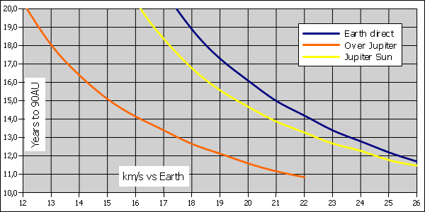
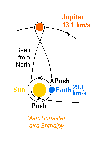
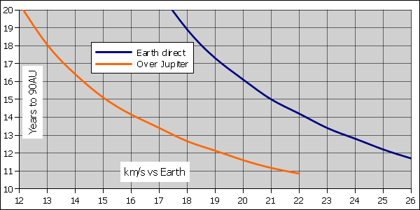
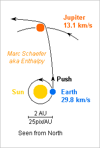
Accelerating nearer to the Sun than Earth is would be more efficient, but if a probe must first brake for that, it gains knowingly nothing. So what if Jupiter sends the probe back to 0.3AU where it accelerates towards the terminal shock? Alas, the flyby must reduce the eastward speed and lose energy. The leg towards the Sun takes time as well. And the net result is: better than shooting from Earth directly, but not quite as efficient as leaving just by the slingshot at Jupiter. TerminationShockJupiterSun.zip Having to operate at 0.3AU in addition to 90AU, the probe becomes much harder to design. It also needs a cryocooler for the hydrogen that makes the second kick, while the simple Jupiter slingshot may conditionally live without. Are there advantages? The same launch can send an other probe in the opposite direction, after Jupiter puts it on a retrograde orbit. Nice, but it takes about 3 years more, and if waiting 5.4 years, a simple slingshot at Jupiter can target the opposite direction too. The deflection by the Sun can vary more, by adjusting the perihelion or by pushing earlier or later. My spreadsheet pushes early. Better: Jupiter can send the probe out of the ecliptic plane, up to polar solar orbits, so the probes can reach the terminal shock in any direction. My spreadsheet computes only prograde and retrograde orbits, but the tilted performance is in between. As the Sun's movement apex is far from the ecliptic plane, reaching this direction may justify the extra engineering and waiting. Saturn seems to achieve retrograde orbits better than Jupiter does, but the legs to it and back take longer. Flybys at Venus, Venus, Earth before Jupiter may save propellant and achieve better angles. I checked none. Marc Schaefer, aka Enthalpy
-
Of the huge speed needed to reach the Sun's termination shock at 90AU in bearable time, a slingshot at Jupiter can give 5 to 6km/s for free TerminationShockJupiterSlingshot.zip so it's time to update the suggested mission of Jul 07, 2013 http://www.scienceforums.net/topic/76627-solar-thermal-rocket/?do=findComment&comment=755396 including as well the improved script for Earth escape of Jul 27, 2014 http://www.scienceforums.net/topic/76627-solar-thermal-rocket/?do=findComment&comment=818683 The future Vega-C puts 3.1t at naturally inclined 400km Leo. Saved 50M$ over Ariane. Sunheat engines raise the apogee to 127Mm radius in less than a year, tilt as needed, end with 2391kg. An O2+H2 engine kicks at perigee to send 1888kg at escaped 4233m/s. The optimum is broad, and more speed saves volume under the fairing. 50kg of chemical engine and oxygen tank are dropped. 1838kg remain. Sunheat engines add 5km/s for 9233m/s. End with 1229kg. 300kg of hydrogen tank and sunheat engines are dropped. 1538kg remain. Sunheat engines add 8367m/s for 17600m/s versus Earth. End with 784kg. Jupiter reached in 0.8 years brings the asymptotic speed to 35km/s versus the Sun. The probe reaches 90AU in 13 years after Earth escape. The remaining 6 D=2.8m engines eject the 754kg in 17 days. They weigh 70kg and the remaining tank 140kg, leaving 574kg for the bus and the science. That's half more than previously with a cheaper launcher - or send 6* more than Vega-C with Ariane. Several smaller probes could observe the turbulence of the medium, sense it by radio transmissions, explore different directions... Jupiter can spread the probes, including out of the ecliptic plane. The probes can also leave Earth's vicinity at different dates. The concentrators can serve as antennas. Each can also collect 1W sunlight at 90AU. If relying on propoer orientation, this is more than enough heat and electricity for a probe that makes a measure and transmission per week, but is little for a parallax measurement probe. Spin stabilisation is an interesting option. Such a mission is the perfect opportunity to test the Pioneer anomaly http://www.scienceforums.net/topic/79814-pioneer-anomaly-still/ Marc Schaefer, aka Enthalpy
-
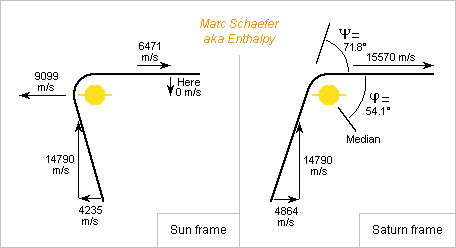
Here's a sketch of the Saturn flyby to join 2015 BZ509. Probes use to overfly planets forwards to get speed, but this script overflies backwards to obtain the retrograde speed. This loses speed, so the propulsion must provide more, in amounts compatible with the sunheat engine. Phi is as in the spreadsheet, Psi is the deflection as in Kate Davis' article http://ccar.colorado.edu/imd/2015/documents/BPlaneHandout.pdf The figures are one example from the spreadsheet, where the probe leaves Saturn with no sunward speed for a cheaper but lengthy strict Hohmann transfer to 2015 BZ509. Other cases can be more realistic, other choices better. Saturn has advantages over Jupiter: The probe arrives with less Eastward speed in the Sun's frame, that's more Westward speed in the planet's frame. Saturn is slower, so the probe loses less speed. The probe gains speed when falling from Saturn to BZ509. Saturn isn't synchronous with BZ509. The launch date and speed adjustments let the probe meet the asteroid, while arriving on time isn't easy with Jupiter. But Saturn moves too slowly to let pick a position, so the probe will improbably arrive at a nodal point of the asteroid's orbit. The correction may demand additional speed which the spreadsheet doesn't include. Combining the correction with the tilt kick or the arrival kick linders the cost. Mass estimates may come some day. Marc Schaefer, aka Enthalpy
-
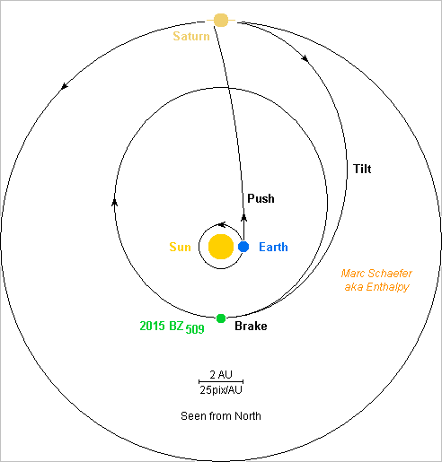
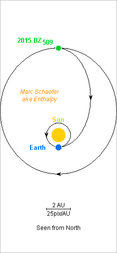
The asteroid 2015 BZ509 is on a Sun orbit as big as Jupiter but retrograde, elliptic and titled https://en.wikipedia.org/wiki/(514107)_2015_BZ509 A recent study suggests that the asteroid is of extrasolar origin, the only matter known in our solar system. So shall we bring samples back from 2015 BZ509? With a reverse orbital speed around 13km/s, the task seems impossible, but the sunheat engine and a flyby at Saturn would enable it, according to my estimates. A flyby at Jupiter instead lets difficulties arise, but I didn't try hard enough: reach BZ509's orbit, synchronize with the asteroid, wait for favourable positions... A solar sail doesn't look good: at one Sun-Mercury distance it takes 18 years to tilt its orbit by 163°, and at one Sun-Jupiter distance it's not autonomous. The probe leaves Earth much faster than for a Hohmann transfer, so it arrives at Saturn in only 2.3 years with much speed in a direction mainly outwards, and passes before and above Saturn which deflects it in a reverse orbit in the same plane (tilt 180°). The minimum global speed cost puts the probe in a Hohmann transfer from Saturn to BZ509, but other options would save time. At mid-transfer, the probe corrects the orbital plane by up to 17°, which is costly, and near the asteroid it makes the final push to accompany it. The Earth-to-Saturn leg is much exaggerated in the sketch: displayed too straight, with the Earth at the wrong place. Reversing the path to come back would need a doubtful combination of positions and cost much speed, so the probe shall head to Earth directly and aerobrake despite the reverse direction. That's about 68km/s, just above the present record, wow. The path is in BZ509's orbital plane, and braking more than Hohmann needs shall let the trajectories cut an other. BZ509overSaturn.zip The spreadsheet contains my estimates. A few uncertainties remain: I computed for Saturn at perihelion or aphelion only, but this makes little difference and the flyby copes with various angles, so intermediate cases should be fine; and I computed for BZ509 at perihelion or aphelion only, but we can't wait until Saturn is at the proper place, and for BZ509 I'm not sure that the intermediate cases are as favourable as the extreme ones. More details and explanations may come some day. Marc Schaefer, aka Enthalpy
-
Hello Internet users! (Should be 100% of the members here) You noticed that all sites, including the very best forums, put for a couple of months a warning that they use cookies - at least for users in the EU. It's not that you were supposed to ignore it. Nor that cookies are deleterious. It's just because the EU has decided that you should not ignore this horrible threat to your private life. Worse: if your reasonable security settings let the browsers erase all cookies at closing, then you get the warning about cookies each and every time. A bit like if the law wanted you not to erase the cookies. The politicians make laws to force companies spy individuals out, for instance reveal all passwords to governmental agencies hence know and store the passwords, which enabled hackers to steal them all at Yahoo. Or to put backdoors in communications, operating systems and so on, making the countries perfectly vulnerable to the alleged enemies. We may wonder if the politicians really should warn us about the companies, or rather the other way. Anyway, I'd to share with you the notice that made my use of Internet a little bit easier: Someone has written for Firefox and others an extension to block the popup warning about cookies It's available there: https://addons.mozilla.org/en-GB/firefox/addon/i-dont-care-about-cookies/ so nice! Enjoy!


