-
Posts
3887 -
Joined
-
Last visited
-
Days Won
1
Content Type
Profiles
Forums
Events
Everything posted by Enthalpy
-

What about superconductors? How to make them small?
Enthalpy replied to jcun4128's topic in Classical Physics
Normal conductors resist lightning very well. The biggest difficulty is a proper Earth connection. The wire is just 1cm2 or so. The trick is that the atmosphere drops the voltage hence the energy; the wire doesn't need to thanks to its low resistance. A superconductor would improve little over copper or zinc, and these work at normal temperature hence are always ready. Superconductors are complicated both physically (we have no theory for all of them) an technically (we can use very few of them because of process or property limits). Their capabilities are strongly limited and this isn't trivial to grasp. The LHC had an excellent introduction online but it has disappeared, alas. Google for "type I" and "type II" superconductor, quenching, and many more. Wiki is of course a good introduction. Most proposed uses for superconductors fail because the inventors are unaware of such limits: residual resistance, Meissner limited to far below 1T and absent from type II, maximum induction, maximum current density, operating temperature far below Tc to sustain the wanted current and induction... Most superconductors are naturally small, like fibres or films. Making them big is difficult. -

Could the Earth Moon system capture another moon?
Enthalpy replied to Moontanman's topic in Classical Physics
Human-intended capture using our Moon must first bring the new object to a very accurate trajectory, yes, because the benefit of our Moon is small. So you may ask if the technology that brings the new object could also capture it in Earth orbit altogether. We're talking about saving possibly 100m/s over several km/s. I using our Moon, the new object should be much lighter, unless this would change our Moon's orbit much, which is frankly undesireable. Ceres is already too heavy for such a scenario. Lagrange's point is at 59,000km from Moon's center, so I feel - nothing more than an impression - that 10,000km is already too far, and that Earth's tides would destabilize the orbit. I've read that no Moon orbit is stable, not even over a few years, but have no opinion about it. There is only one geosynchronous orbit and it's already used... Shall the super technology be already existing, already feasible, or still fiction? I described there http://www.scienceforums.net/topic/76627-solar-thermal-rocket/page-2#entry757109and following message to bring an icy asteroid to Mars' orbit, leaving 11,500t of water there. Earth would be but more difficult. That's far from Ceres' mass, but is a very limited development from our present technology. -
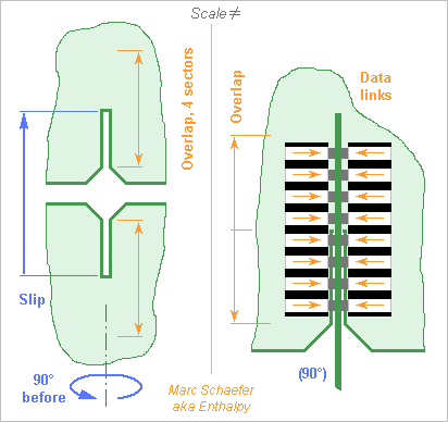
The connections between the processing boards and the cross printed circuits must pass many signals but be narrow and thin to enable close packing. Here the boards and the cross circuits have slits to slip in an other, and the signals use the overlapping length on four sectors to pass. Big printed circuits are flexible, so the slits define the relative positions and must have accurate widths and positions. Added plastic parts would help, easily gliding and maybe with some elasticity. To carry thousands of signals per board, electric contacts would demand a huge insertion force. I consider instead optical links here, with photodiodes and Leds or laser diodes: Sketched for vertically-emitting diodes, but side emitting looks simpler. Plastic parts at each board carry the light, here with an angle that could also result from an elliptic profile; the separator to the adjacent beam absorbs light instead of reflecting it, so the remaining light has a small divergence at the gap between the parts attached to the processing board and the cross circuits. The light carriers could consist of 0.6mm transparent plastic sheet alternating with 0.4mm black one, all glued before the profile is made. At 1mm pitch between the light signals, this would accept, in a direction where printed circuits are stiff, nearly 0.4mm misalignment before the links interfere. Some trick shall index the part's positions at production. Optical chips are small and don't integrate electronics well, so they shall piggyback on a bigger electronics chip, say 9mm long and 3mm wide if shared among adjacent slits. 10Gb/s is present technology. The electronic chips recover the clocks, reshape the pulses, drive the optics or transmission lines, and detect faulty optical links to replace them with redundancy, having for instance 9 optical sets for 8 data links, since light emitters aren't so reliable presently. The mounting method on the printed circuits should allow servicing. 90mm overlap carry 160 signals in and 160 out per slit. A slit every 10mm*10mm is feasible. Other designs are possible. Marc Schaefer, aka Enthalpy
-
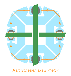
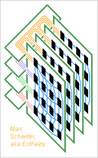
On 02 December 2013 I proposed connectors and cables that run from one board to one other and carry many or all signals between two boards. One alternative would be to choose identical subsets of nodes on each board and have for instance one stiff printed circuit make all connections across each subset: The nature of a hypercube needs no connection between the cross printed circuits, as the processing boards make them, and all cross printed circuits are identical. The subsets can be sub-cubes of the boards or not. A good stack of multilayer cross printed circuits accommodates many signals. This setup typically needs more connectors with fewer signals each for a constant total. It provides a cleaner routing than many big flexible cables and is compact. Numerical examples should follow, as well as connector examples - the sketch doesn't show every signal. The cross printed circuits could have processing boards at two edges, four, more, be circular... but then they're difficult to service. I prefer to have connectors and maybe cables between separate sets of cross printed circuits, as long as the number of signals permits it. As an other variant, the cross printed circuits could be processing boards and vice versa. The computer would then have two sets of boards, say vertical and horizontal, each set completing the interconnects for the other. This needs bigger connectors. Cables remain necessary for the biggest computers. They can complement the cross printed circuits at longer distances. The links from each node heading to a small distance travel with their neighbours in a subset, while the links heading to a long distance travel with other links from the board that have the same destination. Marc Schaefer, aka Enthalpy
-
Here's a better estimate of the consumption of a 64b Cpu, including when slowed down. Intel's 2700K, a 32nm Sandy bridge, draws 95W at 3.5GHz for 4 Avx cores making each 4 Mult-Add per cycle. That's 5.9W per 64b scalar Cpu and includes the refined sequencer, all registers and caches, bus, pins... Intel has a 22nm tri-gate process (5.5W at 4.0GHz) but the combined chips need a process good at Dram. To estimate how much power underclocking saves when undervolting, I refer to http://www.anandtech.com/show/5763/undervolting-and-overclocking-on-ivy-bridge http://www.silentpcreview.com/article37-page1.html http://www.hardware.fr/articles/897-12/temperatures-overclocking-undervolting.html and a mean value is: P as F2.40 down to F/2 and rather as F2.0 below. Having more of slower Cpu saves power, as known from Gpu and Cpu. So this is the estimated consumption of a scalar 64b float Cpu: 3.5GHz 5.9W 3.0GHz 4.1W 2.0GHz 1.6W 1.5GHz 0.8W 1.0GHz 0.4W ---------- How much does the Dram consume? The 5W for Intel's L3 is very bad or very wrong, since four 8-chip memory modules don't dissipate 160W - already the ddr2 modules ran cool, so here's my estimate. The read amplifiers preload the data lines of 500fF each through 5kohm and 10kohm Mos sharing 1.2V; 2048 of them working 1/5 of the time draw 40mW. One 5mm 4*64b 2GHz 0.8V bus to the cache draws 80mW. That would be 0.12W when the Dram works at full speed, quite less than 1.6W for the Cpu. ---------- A cpu with one-cycle 64b float M-Add excels at scientific computing. Though, databases need fast integer comparisons rather than float multiplications, possibly with more Cpu per gigabyte; Lisp needs resemble databases plus a quick stack and a fast Dram random access. Maybe binary-compatible chips with different optimizations target these uses better, say one for float operations and the other for quicker simpler integer operations. More Cpu per chip need more contacts at the package.
-
A giant sauropode could have had several hearts at different altitudes to obtain a decently even blood pressure everywhere. Nature hasn't done it from what I've read, but that would be an engineer's answer. Capillary action also permits trees as tall as Godzilla to live, but maybe it doesn't bring the throughput needed by an animal. Weight of a 40m tall bipedal robot: I have no firm answer neither, because the robot can be built slim or sturdy. 40m is no big challenge for an aluminium construction, even a walking one. For instance airliners can be tall, and they have a big cabin over a tiny landing gear, so there's much engineering room left. Or cranes. Their steel is less efficient than most aluminium alloys, and they can reach far over 40m.
-

Gas Generator Cycle for Rocket Engines - Variants
Enthalpy replied to Enthalpy's topic in Engineering
A deplorable accident reminds us that the F-16 (and seemingly others, as toxicity was feared after a Rafale accident) uses hydrazine in its emergency power unit. No compressor: the pressure-fed liquid (could be a solid) decomposes without oxygen to produce gas at a temperature bearable by a turbine. http://en.wikipedia.org/wiki/Emergency_power_unit#Military_aircraft I proposed here many monopropellants as a gas generator to rotate the pumps of a rocket without the bad hydrazine. A few should hopefully work and would feed the emergency power unit just as well - it's the same task. Upgrades! -
Paraphrasing... The musician brings essentially the same power or energy in the string, but the soundbox permits to transmit more of this power to the air instead of being only lost through air viscosity and more causes. The essential reason for inefficient transfer from a bare string to the air is an impedance mismatch. A solid like the string is dense and stiff, which means a high impedance: it moves with big force and small speed. As opposed, air is light and compressible, meaning a small impedance: a high speed means only a small force or pressure. So a solid like the string, which vibrates with little speed due to its high impedance, and only transmits this speed to the air at the contact area, achieves a tiny pressure and sound power in the air: it's inefficient. A trumpet is louder. A part of the trick is to increase the contact area with the air to move more or it. This is what a loudspeaker's membrane does. To a large extend, a piano soundboard relies on its mere area; mechanical waves propagate in it, most are shorter than the board's dimensions, and they escape to the air over their journey when they're faster in the board than in the air. Since the speed of these flexural (=bending) waves increases with the frequency, such a board gets efficient above a limit frequency; to radiate also low frequencies, the board must be stiff, and this is one advantage of thicker wood with additional stiffeners over metal which is denser hence thinner hence more flexible (there are more differences). By the way, a string can radiate into air through this process, but only the highest frequencies, and only if the sound is faster in the string than in the air. This is a difficult conditions for the material, which must be light and strongly pulled to propagate vibrations so fast. It explains why a string suddenly makes a brilliant sound when you tune it high enough. Few string materials achieve it: good metals, nylon, catgut - and among them nylon dampens too much (other plastics like Kevlar even more and are unuseable, I tried), catgut and metal are good but with a different sound. An other part, for instruments but not loudspeakers, is to increase the solid's speed by resonances - many resonances, because by nature they act on a limited frequency band. This is how a violin's soundbox works, at least at the lower frequencies; the higher are radiated by the wave travelling in the soundboard without reflection nor resonance, and the highest go directly from the string to the air. One of the few things we understand of a violin is that the intertwining of the resonances make a part of the instrument's quality. The lowest resonance is the whole box with its openings that make a Helmholtz resonator tuned around the pitch of the A string; it amplifies the second harmonic of the lowest notes to give a strong and warm sound. Then, the top board comes, and at a higher frequency the bottom one, and again the top the bottom... good instruments alternate them, and regularly spread, well over the 10th resonance, to cover nicely the lower part of the violin's range. End of what is understood from violin's physics, more or less.
-
a) Yes b) The capacitor supplies mechanical work to the inserted insulator, that is, it attracts the insulator. This compensates the decrease of electric energy. This attraction and work is possible because the electric field is not perpendicular to the plates, but has a component parallel to the insulator's movement. Near the edge of the insulator film, the field lines go to the side to plunge in to insulator. They take this longer way through the air because the distance through the dielectric is less costly. b2) The same happens with ferromagnetic materials and coils. In an electric motor, the magnetic field lines flow approximately perpendicular through the gap between the rotor and the stator, except near the slits where pass the wires carrying the current. At the slits, the magnetic field gets tilted to reach the more favourable slit's side. This is where force and work are made, and the magnetic lines have at these locations a component parallel to the movement.
-
One or two Pci-E card can be a data cruncher in a PC to outperform the Cpu (170GFlops and 50GB/s for a six-core Avx). Some existing applications have been ported on a video or video-derived card (1300GFlops, 6Go and 250Go/s), and some other chips are meant for them, but: Databases need a quick access to all the Dram; Scientific computing too, and a Gpu is difficult to program when the function isn't supplied in library; Artificial intelligence runs better on multitask machines, as do most applications. Scalar 64b float Cpu, with the wide access to the whole Dram resulting from same-chip integration, linked more loosely by a network, fit these applications better than many processing elements separated from the Dram by a limited bus. So here's how to cable a bunch of them on a Pci-E card. 256MB Dram per scalar Cpu fit usual applications better than 8GB for 2000 processors. Dram chips have now 256MB or 512MB capacity, so each chip shall carry 1 Cpu, or exceptionally 2. The broad and low Dram responding in 15ns reads or writes 512B at once: that's 3 words per processor cycle. An 8kB Sram caches 16 accesses and responds in 1 processor cycle, the registers do the rest. 512MB Dram chips fit in an 11.5mm*9mm*1.1mm Bga, so a 256MB+Cpu package shall measure 9mm*6mm. I estimate it to draw 1W at 1.5GHz and 0.5W at 1.1GHz. ---------- 256 chips fit on one card, better at both sides, for crest 768GFlops and 8.7TB/s at 1.5GHz. A full switch matrix takes one previously described switch chip. A hypercube is less easy to route; by cabling first 4 chips in a package, the card's Pcb needs about 9 layers. 512 Cpu fill a card much - easier with 2 Cpu per chip - for crest 1126GFlops and 17TB/s at 1.1GHz. A switch matrix takes 4 big packages then and the Pcb about 8 layers. A hypercube would host and route 16 chips of 2 Cpu per 600 ball Bga package, with 8 packages per side on the 10 layer Pcb. A 1024 Cpu hypercube might have 32 chips of 2 Cpu per 1300 ball Bga package, by stacking two chips or populating both sides, and then the card looks like the recently described Gpu with 1024Macc - or double in Sli. If feasible, the card would bring 2252GFlops and 34TB/s, an Sli the double - still at 1.1GHz, needing 500W or 1000W power and cooling. Modules perpendicular to the Pcb hold more chips and are easily cooled. An So-dimm connector with 260 contacts suffices for matrix switching only. A low two-sided So-dimm card hosts 40 Cpu, 24 So-dimm in two rows or around a central fan total 960 Cpu. The switch matrix takes 16 packages (32 per card if Sli) on a thick Pcb, and six sheets of flexible printed circuit can connect two cards. At 1.1GHz, this card offers adaptable 2212GFlops (64b), 240Go, 33TB/s and the double in Sli. ---------- Customers may adopt more easily a new data cruncher than a video card. It needs no directX standard, can integrate an existing Risc Cpu, and many applications are easy to program efficiently for it. The public pays 250€ for 16GB Dram now, so a 1000 Cpu card might sell for 10k€, which many companies can afford. Marc Schaefer, aka Enthalpy
-
The Strasburg cathedral was built on timber, which sufficed as long as ground water was high enough to keep the wood damp. Or Venezia, where some buildings are tall. "in ages with little tools, expertise, [technical means]" With fewer tools and materials and computation means than now, but with very much expertise, and quite a few tools too. They did it as any engineer still does, as a mix of prediction and experience, and being strongly aware of what can be predicted and how safely. Still now, we have no model of how most shells buckle. Spheres under hydrostatic pressure, cylinders under axial or hydrostatic pressure... All models are optimistic by a factor of 2 to 6, oops. How do we manage that? We have to know that models in textbooks are wrong, know where to find good data, and apply rules of thumb and curves with corrective factors learned from experiment. Middle-age engineers probably did the same. Or think of music instruments. We have presently a very limited understanding of what makes them good or bad, to put it mildly. So makers (who are often experts in acoustics, sometimes better than academics) make hypothesis, trials, observations - and most time they stick to what has worked. When you look at how a music instrument is built, it's impressive. The part of it we understand through acoustics tells that it's a fabulously good design - "improvements" suggested by non-makers use to fail whatever the academic knowledge. And then there's all that we know that we don't understand, and the part we even ignore that we don't understand. So having no formal theory is not a definite obstacle to building excellent objects.
-
What do you call a "suit": shall it protect the diver from water's pressure? If yes, it gets so thick that no movement is possible, so it's a hull instead, and so thick that it sinks, needing a separate float. Materials have a strong limit here. The resulting design is not a "suit" to my understanding, but a bathyscaphe. If it transmits water's pressure, a suit wouldn't look difficult to design for higher pressure, but then you must redesign humans.
-
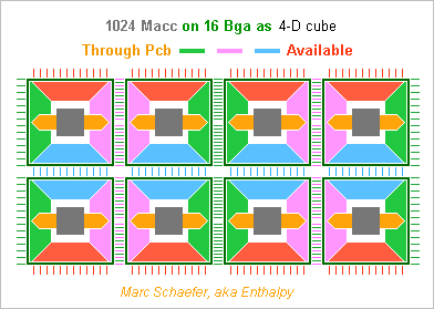
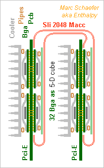
Already the Service Pack 1 for the Gpu... The new front view shows 1024 Macc and the side view 2048 Macc on two linked cards. A video card's height leaves no room around the Bga. The green lines must pass elsewhere. Between two Bga of 64Macc (in one or two chips) plus the rear side are 256 lanes, not 128. The pink and blue dimensions need 4 layers, varied signals 1, plus as many ground or supply planes: the Pcb has already 10 layers. To align 4 Bga, the green dimension passes twice through the card's middle.To route them, the Pcb has 7 layers there, one for other signals, plus as many mass or supply planes: 16, ouch. Or add flexible printed circuits to the stiff board to route the green signals between the card's right and left ends - shows as thin green lines on the side view. 512 lanes fit in four flex with one signal and one ground layers each. The stiff board keeps 10 layers. If passing green signals under the Bga, the orange dimension's lands are distributed to limit the obstruction. Heat pipes (brown in the side view) shall take the heat from the rear side. Copper pillars through the Pcb would have taken much room. Flexible printed circuits can link two cards in a full hypercube. 2048 signals fit in 4+4 wide flex that, at 20Gb/s, transport 4TB/s. The flex are permanently welded on the Pcb and demand a strong mechanical protection. Some elastic means holds the Pcb permanently together. Can we exaggerate? As described, each Macc node can exchange 20Gb/s in any dimension, or two words in 8 cycles. I feel a Gpu accepts less, and because the links are reshuffled at the chips, we can have fewer links and then more chips, or more Macc per chip. Marc Schaefer, aka Enthalpy
-
Obviously, French politicians are unable to understand the unreasonable risk, or unwilling to resist some obscure appeal. Ségolène Royal, minister for environment and energy, declared yesterday that France needs to develop Astrid, a fast-neutron reactor. (Remember the industrial disaster of the EPR, still not working, whose penalties for late delivery already exceed the sale price. Remedy: develop Astrid in addition.) A reactor in operation is "critical": its neutron flux is at equilibrium thanks to (1) natural retroaction that reduces the reactivity if the temperature increases (2) man-made hence slow retroaction, only fast enough to intervene on the "retarded" neutrons, which make <1% of the total with plutonium. If some external action increases the reactivity by 1%, means of human control are lost, and the natural retroaction has a limited efficiency too. Worry: a fast neutron reactor lets a big proportion of neutrons escape the core; opacity to this flux is paramount to the core's reactivity, and it depends on the core's density. This is how a plutonium bomb is started, by implosion. This is also how a big kinetic impactor would detonate a fast neutron reactor: by compressing it. At 3km/s, the impactor would compress the plutonium/sodium suspension by 30% easily, and even separate the sodium and plutonium, so that the reactivity jumps by far more than 1% How big the following nuclear explosion is remains unclear. The compression is damned quick, faster than in a bomb. 100 to 1000 time more plutonium is available than in a bomb. But the shape of a reactor core isn't optimized to detonate, nor is the impact at the worst possible location and angle, so I expect the nuclear explosion to take place but use only a part of the available plutonium. Then, you can expect an enemy to add worsening materials in the projectile: a "booster". This doesn't even demand nuclear technology. Such a scenario looks really bad. Angela has a PhD for nuclear physics, and Germany closed its fast-neutron reactors when I drew public attention on this risk. But French politicians have a degree for politics.
-
Yes, I proposed it years ago and wasn't probably the first. It has been prototyped meanwhile and abandoned for unclear reasons. I still believe it's the best way to recharge car batteries: replace them. Capacitors? Their capacity is far smaller than batteries. Useful to store the quick charge/discharge of regenerative braking, and use on autobus.
-
In addition to - Condensation not necessary, railway engines don't condensate - Clean water protects the boiler against scaling, and a closed cycle keeps water clean - Pumping liquid water back is better than vapour - Condensing at <<100°C hence <<1atm improves the efficiency I wish to add that most steam engines let some vapour condensate during the expansion, not only at the condenser. - This is unavoidable where the source temperature is bad, that is at water-cooled nuclear reactors. Pressure must be high for good expansion, so the initial vapour is nearly saturated, and some condenses very early. Nukes have a vapour dryer and a re-heater between the high and low pressure turbine stages. - This early condensation improves the motor's efficiency, as opposed to what most textbooks claim. It makes good use of some heat used to evaporate the water. Without it, simple figures tell that nuclear power plants couldn't possibly achieve their observed efficiency. - But the droplets' high-speed impact wears the blades more quickly. They need an adequate alloy and must be replaced more often. One may also note that gas- and oil-fired power plants have a combined cycle, where the gas burns in a gas turbine whose exhaust heat powers a steam turbine - plus many heat exchangers, pre-heaters and so on meanwhile. This achieves well over 40% conversion. This is more difficult with coal which can't burn within a gas turbine, but because coal is cheap, plants exist that first transform coal (using water) into a liquid or gas that can burn in a gas turbine. One may also wonder if water, needing much heat to evaporate, is the best choice. The answer is "yes" at usual flame temperatures, especially thanks to all the added exchangers and pre-heaters. At low temperature, say to exploit the temperature difference between the Ocean's surface and deep water, other fluids like carbon dioxide are better. The non-obvious comparison results from complete cycle computations including technical losses. The condenser is a very difficult part of a power plant. It must treat huge volumes of vapour (pressure as small a possible), drop as little pressure as possible, drop as little temperature as possible, but transfer a huge heat power. Where no river suffices to cool the plant, the cooling tower is the other very difficult part.
-

Understanding The Squirrel Cage Induction Motor.
Enthalpy replied to CasualKilla's topic in Engineering
An induction motor needs resistance a the rotor to work. Those with contact rings had an external resistor to help starting, squirrel-cages rely on the conductors only. As already noted, the stator's field would induce currents in the rotor that oppose the stator's field, that is, the toro's field would be parallel (and opposed) to the stator's one, which creates zero torque. The rotor has also a leakage inductance that makes the rotor's reaction slightly smaller than the cause, but being inductive also, this leakage brings no help to the phase and angle of the rotor. The rotor's resistance introduces a phase dfference between the stator's field and the rotor's reaction. In the rotating fields, this phase means and angle between both fields which results in a torque. Absolutely necessary. At high slip rate, say when starting, the rotor's reactance augments because its self-inductance sees a higher frequency (the supply frequency minus the rotation frequency, smartly adjusted by the number of poles). Then the loss resistance can't achieve a good angle between the fields and the torque diminishes. So unless the motor rotates a fan, it needs some trick to increase the resistance when starting. - Some squirrel cage motors have several cages; where the shallow one has a higher resistance to bring torque at start, and the deeper one works only at smaller slip frequency to reduce the resistance and improve the efficiency. - Ring motors have the external starting resistor, which can be regenerative electronics to save energy. - Presently, all motors above few kW have drive electronics to produce the optimum three-phase current. Squirrel cage motors are driven with the optimum frequency and voltage that guarantee a big angle between both fields, to obtain the desired torque with minimum currents and losses, even during acceleration and braking - called vector drive. So well that ring motors have disappeared, synchronous motors nearly so. -
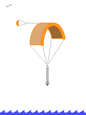
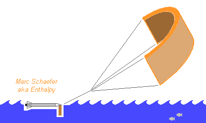
Here are, very late meanwhile, at least drawings to explain that the paraglider that splashes the booster on the Ocean also sails it back home, usd as a propelling kite. Kites serve already to propel cargo boats and are highly automated: http://www.skysails.info/english/ in gently trade winds, they would cover 500km in 2 days. Perfect at Tanegashima, Kourou... maybe at Cape Canaveral, Goheung and Sriharikota depending on the traffic. Bad idea at Baikonur. Pressure-fed liquids combine well with reused boosters navigating the Ocean: they are already as strong as a boat hull, they float and keep clean... This makes them better candidates than solids, and they are more efficient as well. Sailing back takes no additional fuel, is technically simpler than flying, needs no wings, engine, landing gear, and the certification and integration to traffic is easier for a boat.
-
The Press reports that a studied variant of Ariane 6 has a reuseable first stage, stronger to fly with 0 or 2 boosters where the Vulcain-pushed stage would take 2 or 4. This reused first stage would burn methane with oxygen. My two cents worth of comments: Cyclopropane is as efficient as methane at equal pressure but denser, so the turbopump achieves more pressure. Strained amines that don't burn at room temperature lose only 4s to cyclopropane and methane. Pmdeta must leave the jacket cleaner than kerosene does, cis-pinane maybe. Both are better available, more efficient, and safe. Cooling the jacket with oxygen isn't done now but it would leave the engine clean for reuse. It permits ethylene that outperforms cyclopropane and methane by 2s, and in an expander cycle, safe fuels. I'd already have proposed reuseable pressure-fed boosters for Ariane 6 if data about mass and dV were public http://www.scienceforums.net/topic/65217-rocket-boosters-sail-back/ with oxygen and Pmdeta, sailing back using the paraglider as a kite.
-
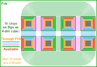
Some details about the video card suggested on 07 January. The individual 4MB Dram must cycle faster than 15ns, like 4ns. The transfer size to the cache can then be smaller, say 128B. The Sram cache is fast, and it can be smaller than 8kB. E8600's 32kB takes 3 cycles at 3.33GHz, so 8kB must achieve 1 cycle at 2GHz. A single cache level suffices, both for a load-store architecture or for operands in the cache which could optionally be a set of vector registers. Prefetch instructions with the already described scaled indexed and butterfly memory addressing keeps interesting for Gpgpu. The network within a chip is easy. Two layers for long-range signals, of 200nm thick copper and insulator, diffuse the data at roughly 25µs/m2. The lines can have two 15ps buffers per 1.5mm long Dram+Macc node, plus some flipflops; they transport >10Gb/s each and cross a 12mm chip in 500ps - just one Macc cycle. One 20% filled layer accommodates 90 lines per node over the full chip length, so Each path can have many lanes; The on-chip network isn't restricted to a hypercube; Each node can reach any position and any bonding pad on the chip. So all nodes in one chip can group their links to one other chip at some subset of the bonding pads, and routing the links on the board is easy - here a sketch with a 2^4 hypercube. Better, some permanent or adaptive logic can re-shuffle the links before the pads to Change the pinout among the chips to ease the board; Replace faulty pads or board lanes with redundant ones; Allocate more links to the more needy Macc; Spread optimally the data volume over the cube's multiple paths. Now the number of Dram+Macc nodes per chip depends less on the number of pins. As a model, the 131mm2 Core i3-2100 has 1155 pads, which permits ~250 bidirectional links and needs for instance 3 signal layers with 4 lanes/mm and 4 ground or supply layers just to reach the pads. A ceramic board could do it, but the Lga-1155 package achieves it with "resin and fibre". 100µm wide lanes would introduce 20ohm losses over 100mm distance at 10GHz (~20Gb/s), so a 4 to 32 chips module could have one single ceramic or printed circuit board (Pcb) substrate with 4 lanes/mm, needing few external pins if it concentrates all nodes of a video card. Alternately, a first fine-pitch substrate can carry one or few chips in a package and a coarser board connect the packages. A Pcb with 2 lanes/mm on 3 signal layers and 4 ground or supply layers can connect a 32mm*32mm Bga and connect 16 chips on a video card as sketched, for 1TB/s between hypercube halfs. 5 signal layers would save space and 7 permit 32 chips. This Pcb with 200µm wide lanes transports 20Gb/s over >200mm and is cheaper. The same Pcb could even stack finer layers used near the chips over coarser ones for longer distance. Probably more expensive than Lga distinct from the Pcb. Beyond video cards, also parallel computers can have several computing nodes per chip as far as the Dram suffices, and the proposed solutions apply to them as well. Marc Schaefer, aka Enthalpy
-
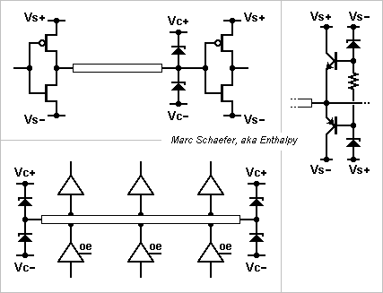
This is a propagation line termination without steady losses. Other people may well have known it, but I've seen no description up to now. Related with connections in computers, but not especially with supercomputers nor with processors spread among the memory. The data transmitter is a push-pull, on the sketch a Cmos. The line's opposite end has no resistor but two fast clampers. There, the incident wave rebounds and exceeds the logic levels Vs+ or Vs+, just slightly thanks to the clampers. The small reflected wave comes back to the transmitter where it approximately extinguishes the transmitted current. Some small oscillations happen but are acceptable. Next, current flows nowhere and no power is lost; the only consumed energy charges the line, which is optimum. As fast low-voltage clampers, silicon Schottky spring to mind. For 0/5V logic they can divert the clamping current directly in the supply rails, but at 1V logic they better have they own clamping rails Vc+ and Vc+ a bit within the logic levels to minimize the overshot. The chip's built-in electrostatic protection is too slow for this use, and Schottky's low voltage avoid to turn it on. Bipolars (chosen strong against base-emitter breakdown) can avoid the additional rails, as sketched; if the diodes conduct at 0.4V and the bipolars at 0.7V, they clamp at 0.3V outside the supply. A bidirectional bus with tri-state buffers can use this scheme, as sketched. Additional clampers on the way would neither serve nor hurt. Pin capacitance has the usual effects. A differential line could use this scheme; though, push-pull buffers inject noise in the supplies. Marc Schaefer, aka Enthalpy
-
The memory throughput of video cards mismatches their computing capability presently. For instance, the R9 290X (the GTX Titan Black is similar) computes 2816 billion multiply-adds per second (2816Gmadd/s) on 32 bits numbers, but its Dram ouputs "only" 80 billion numbers per second; depending on how many new numbers each Madd takes, that's 70 to 140 times less, and it gets worse with newer models. The Gpu (video processors) have faster internal caches. Maybe the emulation of directX 9 instructions for my older games on directX 10 Gpu doesn't use the caches well, but my tests tell that the Dram throughput determines 90% of a video card's speed, and the computation power 10%. Here's hence how spreading the processing cores among the Dram - often in several chips - would improve this, compared at similar computing capability. Take 1024 multiply-adders (Madd) at 2GHz for 2000Gmadd/s with individual 4MB of Dram close on the chip. The small Dram units can cycle in 15ns, so accessing 512 bytes (4kb or 128 words) for each transfer to and from the cache provides 4.2 words per Madd cycle, totalling pleasant 35000GB/s. An 8kB cache would store 16 transfer chunks for 3% of the Dram's size. A hypercube shall connect the 2^10 nodes since I haven't found advantages to hypertori and others. Package pins limit to 64 nodes per chip; 4+4 serial monodirectional chip-to-chip links per node take already 512 signals (and the 6+6 links within the chip take none). At 5GHz like Pci-E 2.0 or Gddr5, the hypercube transports 640GB/s through any equator, twice the Dram of existing cards. In this example we have 2*64 link between chip pairs. A few redundant links could replace faulty chip i/o or Pcb lanes. With 3 billion Dram transistors and 64 nodes, the chips are "small". As extrapolated from both 2800 Madd Gpu or quad-core Avx Cpu, they would dissipate <10W per package, far easier than presently, and permitting the 2GHz. Though, wiring 16 large packages per card needs denser Pcb than present video cards; package variants with mirrored pinout would help. Cards with less computing power and memory can have fewer chips. The cards may have a special chip for the Pci-E and video interfaces. While the very regular programming model with few restrictions must run many algorithms well, it differs from dX9, dX10 and followers, so whether existing software can be emulated well remains to see. How much the data must be duplicated in the many Dram, as well. How to exaggerate further? The nodes can exceed 2GHz, to compute faster or to reduce the number of nodes and links. Transmit faster than 5GHz: Pci-E 3.0 does it. The links could have been bidirectional, or less bad, several nodes could share some links. If general enough for a Gpu, the nodes can multiply quadrivectors instead of scalars. Marc Schaefer, aka Enthalpy
-

Gravitational Interferometer and Kalman
Enthalpy replied to Enthalpy's topic in Astronomy and Cosmology
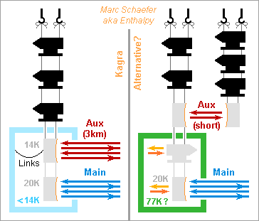
Cooling by light needs the de-excitation to be almost always radiative, and meanwhile I doubt that shallow acceptors in a semiconductor de-excite radiatively: angular momenta may well forbid it. A three-level scheme should be better, where heat populates partly a shallow acceptor level, light brings electrons from there to a level deeper in the forbidden band with the proper angular momentum, and fluorescence takes the electrons back to the valence band most often because an additional acceptor depletes it. A quantum well is an alternative to the shallow acceptor. ---------- The sketch represents auxiliary light cooling the main mirror, as compared with Kagra's design on the left part. Light with slightly too weak photon energy impinges on the cold parts which radiate by fluorescence. Kagra holds the main mirror by sapphire cables, but here they isolate from heat, so they're thin and rather of a different material. I've drawn one additional stage at intermediate temperature. As no metal wires that extract heat from the main mirror inject thermal noise, the auxiliary mirror can be warm and farther upwards in the suspension chain, then with a less sensitive measure there. Kagra needs <14K to evacuate heat at the auxiliary mirror, and then putting the whole cryo chamber at that temperature that reduces the thermal noise is a logical choice - or do you see an other reason? 77K would radiate very little heat into the main mirror, the parasitic radiation at 1060nm is faint and cool baffles can attenuate it, so 77K or even warmer would be a nice simplification. A supercritical cooling cycle for the chamber would be quieter, or maybe my "electrocaloric bucket brigade device" if it works meanwhile http://www.scienceforums.net/topic/78682-electrocaloric-bucket-brigade-device/ Cooling the mirror by light needs that the transition's energy exceeds the chamber's temperature. Though, the transition's energy should not exceed the mirror's temperature too much, because it determines how much fluorescence power the chamber must evacuate: if the mirror's heat provides for instance 5% of the radiative transition energy, the chamber must evacuate 20x more, or 10W - easier at 77K than 0.5W at 14K, but some transition energies are better than others. Marc Schaefer, aka Enthalpy -

Gravitational Interferometer and Kalman
Enthalpy replied to Enthalpy's topic in Astronomy and Cosmology
Kagra's main Fabry-Perot mirrors absorb 400mW of the light, to be evacuated from 20K where radiation would be difficult. Kagra foresees several wires of pure aluminium, thin and long so their thermal noise shakes the mirrors very little. Far less simple, but it should be quieter: I suggest to cool the mirrors with light, about like ions are cooled in a trap. This straightforward idea may well exist already. Light-emitting diodes can in principle do it: when their forward voltage is less than the bandgap, heat provides the missing energy to the electrons, and the emitted photons carry away both contributions. Under normal conditions and a special design, a net effect must be achieveable, when the quantum efficiency exceeds the bias-to-bandgap ratio. Maybe useful elsewhere; here it would better use a small bandgap material like InSb (already 240meV while 20K=1.7meV) or Sn, possibly heterojunctions - and worse, it needs electricity, not good here. Absorbing and emitting light looks more promising. The source brings photons of energy just smaller than the transition, heat does the rest, the sum leaves the mirror. But because kT is only 1.7meV, this demands a small transition energy and a good quantum efficiency. Here are some configurations, maybe one will work. The mirror's sapphire might receive colour centers, say at the back side. If fluorescing at 1060nm, they could absorb photons with 3kT less or 1065nm, so a net cooling demands 0.996 quantum efficiency, err... Smaller transitions would be better. But at least the mirror stays monolithic, which minimizes the thermal noise below the mirror's resonances. Introduce light in a thin layer from which only antistokes wavelengths escape easily. How inefficient? Have a layer of InSb. At cold, its direct 240meV gap radiates 5.2µm photons and can absorb around 233meV. Net cooling would demand 0.97 quantum efficiency, but InSb isn't a great light emitter. http://www.ioffe.rssi.ru/SVA/NSM/Semicond/InSb/index.html Use Sn instead. Figures vary; the gap could be 60meV. Is it direct? InAs has 415meV direct gap at cold, but it makes superlattices with GaSb, offering transitions small and adjustable at will. Absorb light at a not-so-shallow dopant level. Some 15meV to the band avoid ionization at 20K. InSb has usual dopants at 10, 28, 56, 70meV from the valence, InAs at 10, 14, 15, 20meV, Si at 45meV. 4*kT is 24% of 28meV, better. Could F, N, Si, Mg be shallow dopants of sapphire? To remove the wires, light must achieve all the cooling, starting at 300K. This may need a set of transitions energies or source wavelengths. If using a 28meV shallow level, the 5THz source is uncomfortable presently, but for 4K and 5meV instead, the source at 1000GHz is accessible to semiconductor components: 100GHz with transistors, multiply with varactors. Waves so much longer than the 1060nm signal should be filtered out. If not, alternate cooling and observation? The mirrors absorb 1ppm of the measure light, so even if only 0.1% of the cooling light evacuates heat, the added noise from the radiation pressure is small. The cooling light can be spread at will on the mirror, statically or by scanning, perhaps even on the front side thanks to the different wavelengths, in order to minimize thermal gradients in the mirror. Marc Schaefer, aka Enthalpy -

Gravitational Interferometer and Kalman
Enthalpy replied to Enthalpy's topic in Astronomy and Cosmology
The Kagra or Lcgt project, a cryogenic gravitational wave interferometer being built at the Kamioka mine in Japan http://en.wikipedia.org/wiki/KAGRA shows a secondary mirror and beam in but-last position of the suspension chain, resembling much what I describe. See figure 4 of: "Present status of large-scale cryogenic gravitational wave telescope" Class. Quantum Grav. 21 (2004) S1161–S1172 and also figure 4 of: "Status of LCGT" by K Kuroda Class. Quantum Grav. 27 (2010) 084004 (8pp) These texts detail little the function; the secondary beam shall sense and actuators shall lock the position of the upper mirror too, so that the metal wires that evacuate the heat from the mirrors don't introduce ground movements into the main mirror. Apparently it's not a part of a Kálmán filter, and the secondary beam is as long as the primary. Virgo, the gravitational wave interferometer in Italy http://wwwcascina.virgo.infn.it/ doesn't show secondary mirrors nor beams. No details about Advanced Virgo https://wwwcascina.virgo.infn.it/advirgo/ Nice theses about the suspension, plus general information: https://wwwcascina.virgo.infn.it/theses/Tesi_Ruggi.doc https://wwwcascina.virgo.infn.it/theses/DottCasciano.pdf


