-
Posts
3887 -
Joined
-
Last visited
-
Days Won
1
Content Type
Profiles
Forums
Events
Everything posted by Enthalpy
-
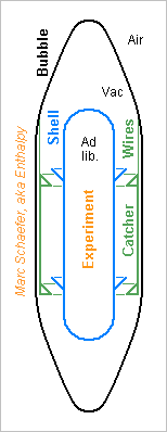
The slightly tilted lower portion of the railway, suggested on Oct 25, doesn't work. Changed my mind for the (2N+1)th and hopefully last time. But pushing slightly the experiment eastwards at take-off within the vacuum bubble would. ---------- This is how the free-float within the vacuum bubble could look like. Only a suggestion needing more ideas to be a viable concept. And since the experiment shell is only 1m wide for 0.2m radial free-float margin on this sketch, I'd add 1m to every radius up to the windshield tower. During gravity, acceleration and braking, the experiment shell rests by cones or cone segments on a catcher that holds at the vacuum bubble. The experiment shell takes off the catcher by ~0.2m after the acceleration, for instance because the scoop control let the bubble be late. Few meters before braking, the scoop control slows down the bubble to land the experiment shell in the catcher. The catcher is stiff vertically but moves easily to the sides. For instance a suspension under 1m solid steel wires gives at 15g a 0.5s period, longer than the complete acceleration, so that shocks at the railway during the acceleration are filtered out, and the experiment shell starts its free float with a precisely vertical speed. When landing excentered, the experiment shell hits only the light catcher, which can have lateral rubber bumps in the vacuum bubble beyond its free movement, so the contact shock at the experiment is small. Instead of hanging under wires, the catcher could roll on two-dimensional ball slides. The catcher could have lateral actuators, and then optionally be narrower and follow actively the experiment shell. This would reduce the lateral acceleration at landing, as the catcher would center the experiment after braking, and could also linder the Coriolis drift by acting during the acceleration. It would also gain diameter at the shell. It needs very soft actuators, possibly through rubbers, to transmit no shock from the railway. The catcher needs lateral dampers if not actuators. The catcher could have a vertical actuator; for instance ball screws are fail-safe. Then, the catcher can actively move down to begin the free-float phase and move up to land the experiment shell. This reduces the vertical shock at landing. More active catcher designs are possible, but they must be very stiff to impart no side speed to the experiment shell - metal cones are good at that - and must insulate the shell from the railway shocks. The experiment's angular speed after take-off is also critical, like 0.1°/s, for good microgravity - again in favour of metal cones. For 1000 flights a day, the catcher must behave gently when its control fails. I'd rather leave some clearance between the wheels and the rails over most of the track. Though, the acceleration and brake segment can have thicker rails if made of single parts, in order to suppress the play there. The thickness transitions must be very long for 180km/h. I suppose the wheels can have a suspension. Several experiment shells, possibly several vacuum bubbles, accelerate the experiments turnaround. Marc Schaefer, aka Enthalpy
-
It has been done, for instance at one old Cray supercomputer immersed in liquid nitrogen. This method is avoided whenever possible: It's dirty. Commercial components are not tested to work in a liquid. Electronics engineers badly want to access the boards, and even the components, when it's in operation at its final position with its final connections. Mandatory to assess and correct electromagnetic worries. Already the integration as a rack is bad and leads to boards that work approximately for being difficult to observe and tinker. As opposed, the satellite-type integration cools the components well enough for a computer and offers a decent access. Where needed, heat pipes are more efficient than a liquid bath and are clean. They suffice for the worst processors and even for radio transmitters on satellites. The method presently, for supercomputers too dense to be cooled by air only, is to conduct heat away from the components through metal to pipes where a liquid flows actively. I suggest elsewhere to develop long branched alkanes similar to phytane for that purpose; they would have more uses, like transformer oil, hydraulic fluids and lubricants for aeroplanes and vacuum machines.
-
Thanks for your interest! A decommissioned mine shaft looks an interesting option. I easily agree with it because I suggested it here on Sept 30, 2014. I checked the coal mines in Germany, where the last ones are closing, and they're commonly 600m deep, which would double the flight time. Difficulties: People willing to conduct microgravity experiments are not always where abandoned mines are. At least in the densely populated Germany, the shafts are filled when a mine is abandoned. Many shafts are tilted. Are the vertical ones straight and broad enough? I haven't found accurate descriptions of that. At many places, mine shafts use to fill quickly with water and stones. A plan of a cave appeared on the Internet few days after I suggested here on Sept 30, 2014 to use a tall cave or mine... A natural cave >150m tall is a natural marvel. I wouldn't damage it. Some mines can be really tall. Maybe salt mines (but natural and manmade marvels again), diamond mines in South Africa (miners let the ceiling collapse to gather ore), some mines in Canada, and more. How dangerous the place is remains to check... I like an oil well less for the symmetric reason... The bore is narrow and usually skewed. Does it withstand the pressure of stone and water? I believe not, even after cementing. Oil-well operation takes great care to keep the proper mud density in the well to avoid its collapse. The new user would have to separate the bore from the oil or gas reservoir and empty the bore if feasible. Oil-well operations are expensive. A tower isn't difficult nor very expensive with the materials I suggested, and can be built about anywhere. It can exceed 150m easily, and if aviation dislikes that, the tower can be built from a pit. Finally, a mine or mine shaft may be better or cheaper, but it depends much on a lucky finding.
-
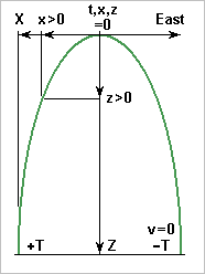
Earth's rotation lets the free-floating experiment drift during the flight, hi Coriolis. The vacuum bubble must offer enough room for this drift. But how much? At arbitrary 53° North, the ground rotates at a=43.8µrad/s around the meridian. The bubble's eastward speed increases as height*a, while the experiment's eastward speed decreases as height*a, because the experiment's angular momentum versus Earth's center is conserved: http://en.wikipedia.org/wiki/Kepler's_laws_of_planetary_motion With these axes orientation and origin the difference of east-west speed between the bubble and the experiment is when the flight starts from the ground - this matters. Integration from t=0 to the half-flight duration T gives the half-flight westward drift X or 2X=97mm for Z=150m. ---------- This Coriolis drift can be lindered against varied criteria. For instance, the experiment would land at the center of the vacuum bubble if it takes off with 9mm/s eastward, and would then drift most near apogea. Some mechanism could pull the experiment gently to the side during the acceleration, or more reliable, the railway could be permanently tilted by 1.7mm over the lower 10m. This, of course, if no other cause overshadows the 97mm and 9mm/s... Marc Schaefer, aka Enthalpy
-
That's your present opinion, but not the one from Newton and Kepler, unfortunately. As a craft on its orbit goes farther from Earth, its azimutal speed (in m/s, not just angular) slows down. That's the conservation of angular momentum. It's one of Kepler's laws. What's not completely intuitive here is that Earth's attraction slows the craft down. It seems that the vertical force shouldn't act on the horizontal speed, but in fact it does, because the "vertical" and "horizontal" rotate along the trajectory.
-

Challenge to received understanding of the Coeff of Static Friction
Enthalpy replied to Enthalpy's topic in Speculations
For knowledge as accessible and well-spread as coefficients of friction, I feel it overkill to look for one source. The tightening torque for screws is in any book or handbook for mechanical engineering. Having used friction for years on a daily basis to design about everything in crash-test hardware, accumulated many paper and digital sources and tables on the topic, and having measured by myself because sources aren't so reliable, I don't really feel the need to point at one research paper or book. It's a bit like telling that bread is baked: one wouldn't ask for a peer-reviewed source about it.- 16 replies
-
-3
-
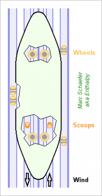
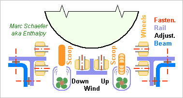
Here are some hints about how to guide a shuttle - for a vacuum bubble surrounding a free-floating experiment, not for an experiment falling in a vacuum tube. Plain bearings are doubtful at 180km/h, so I consider polymer wheels instead, especially polyurethane that absorbs small bumps and misalignments. They're good at 120km/h; azimuthal or radial fibres as in tyres could reinforce them if needed. The sketches, side and bottom views, are not to scale: The wheels roll against rails separated from the truss to permit a finer alignment. Pouring some resin or concrete between the rails and the beams would bring stiffness if needed. This arrangement of wheels and rails lets clearances depend little on the truss' dimensions; a pre-load is possible. For quick repetitive operation, an electric linear motor as well could compensate the drag, but I've sketched the scoops and the wind channels instead, here with still another arrangement of the fans. Small hydraulic turbines could rotate the fans, as an alternative to the means already suggested. Marc Schaefer, aka Enthalpy
-
The cube is correct for a dipole, I confirm. Remember this is for a static field or slowly varying. If the charges, currents... vary significantly within one propagation time between the poles, then you obtain a part as a propagating field which decreases less quickly.
-
In technological capacitors, the leakage current uses to be a far minor cause of losses. It can be significant in very special constructions, for instance in propagation lines for huge power that use pure water as a dielectric. Even in DC or extremely low frequency uses, the volume resistivity of a decent insulator is generally not the primary cause of leaks. Leaks appear first in the external circuit, then at the surface of the capacitor component, then along the surface of the insulator film, and only then through the insulator's volume. So much that measuring the resistance of a good insulator (polystyrene, polypropylene...) is extremely difficult. For practical uses, and in the datasheets, all losses in the capacitor are represented by a resistor (generally in series) or by a quality factor. This resistor is not physical and it varies quickly with the frequency. At low frequencies, the first cause are losses in the dielectric, not due to leakage, but due to the slow and lossy response to the external field. If ions move as a result of the field (and the heat) in electrolytic capacitors and type II and III ceramic, they do it slowly, so the capacitor appears in part as a resistor. This tells that such components work only at low frequency. Polyester film capacitors too use some small atoms movements to increase the permittivity and are limited to audio frequencies more or less. Faster dielectric are non-polar, like polypropylene, polystyrene, polytetrafluoroethylene... though a few polar ones like epoxy, type I ceramic are UHF capable. Non-polar dielectrics absorb also less humidity. At VHF and beyond, type I ceramic coexist with capacitors made by the printed circuit, of glass-epoxy or (SHF+) PTFE. Due to skin effect (1µm @5GHz for Cu), losses arise much at the conductors then. That's why SMD capacitors for VHF+ have terminations coated with expensive palladium instead of the ferromagnetic nickel used at lower frequencies. Losses, together with the self-resonant frequency, determine which capacitor technology fits a given frequency. The available capacitance and quality factor constrains heavily the design of a VHF+ circuit. Even at audio and metrology frequencies, detailed knowledge of capacitors capabilities (that's more than losses) is necessary.
-

Challenge to received understanding of the Coeff of Static Friction
Enthalpy replied to Enthalpy's topic in Speculations
Engineering by thousands of people make a claim properly supported, far better than any publication. Have a look at the torque used to tighten screws, these tables work, I did the measurements. Or put an object on a banked surface and observe the slipping angle. I did. The coefficient of friction is regularly around 0.2 to 0.3 for metals, even for this small pressure. One other argument against the shear-to-compression ratio theory is that also the hardest material influences the coefficient of friction. Say, polished chromium and nickel coatings are way harder than bronze, and they show different coefficients. -
Why do you imagine a change in the gravity field when the outer mass accelerates outwards? The mass+energy is conserved, and if the objetc stays symmetric, the gravity we experience from it repends only on its total mass+energy (which gives the flux) and its distance. Which is the reason why standard theory precludes axial gravitation waves. The authors did NOT write a "symmetric" supernova explosion, that's why they write "gravitational wave".
-
Collapse time: about as short as a lightning strike. Wider: no, it's a matter of power and energy. Present experiments are already at the exaggerated limit. Improve, increase... I see no means, and doubt there is one with present technology.
-
Thanks for your interest! A 150m tall and 10m wide vacuum tube is simple before it's developed, built and operated. Once you give some engineering thoughts at it, it gets nasty. Certainly worse than the railway truss, and I'd say (...until the serious engineering worries pop up...) worse than the approximate drag compensation. Remember I consider a free-floating experiment, so the enveloping vacuum bubble doesn't seek high-quality microgravity, and without compensation at all it would drift by only 2m. For instance, the tube at Bremen takes 1.5 hour to evacuate. I still ignore the operation details, but the free falling experiment is braked by crushed material. This makes it difficult to catch and put the experiment in place for the next flight - maybe it happens in vacuum, maybe it need humans. As opposed, a guided vacuum bubble can be caught automatically (it's really difficult at 180km/h!) and be ready for restart in less time than a flight. This means that experiments can accumulate data for most time. Some experiments can take advantage of that and do need much flight time, for instance atoms interferences. <10s reload and 10s flight alternating for one day would be hugely better for them than 10min or 1h reload alternating with 10s flight. I haven't put figures yet, but it's possible that the vacuum bubble that moves with the experiment gives a better microgravity than the experiment falling through a fixed "vacuum", as the remaining air has zero point little relative speed instead of 50m/s. To me, the mobile vacuum bubble looks like a game-changer that brings a drop tube radically better capability. ---------- Maybe I should have made clearer that not all the messages here apply to to the moving vacuum bubble. Many are for an evacuated drop tube: the extruded walls, the airlocks...These would not add their complexity to the moving vacuum bubble. A catapult exists already, at least in Bremen, to double the fight time - same complexity at the moving vacuum bubble. And if bungees double-serve as brakes, the combination can be simpler, especially as they permit a quick restart. So a guided mobile vacuum bubble adds the bubble, the drag compensation, the railway - but saves the big vacuum tube and its airlock or huge pumps.
-
Hi, the canopy first drifts quickly downwind, it pulls the load to the side, which may oscillate for some time, until both descend vertically with respect to the air, that is, at the same horizontal speed as the wind - provided the wind hasn't changed meanwhile. Was that the sense of your query? Or rather the air flow at the surface and the deformations? Something else?
-
Puzzling idea... ESA has had similar thoughts, but for the Moon and Mars, and a nice demonstrator works (on Earth). Their goal is to use regolith to make houses. They melt this dust with a laser to make a compact stone. Delays are accepted. It must be possible to place steel elements by a robot instead of melting them. Robots are capable enough for it. Or make the building of steel only. Not uniformy thick: with beams, and ribs, and sandwich panels resembling a flat bone. Have you thought further at how you contain the concrete once it's deposited and before it's hard? Stereolithography does it either by depositing a complete layer that is cured only when the solid shall stay, or by depositing the material in small amounts and curing it (or solidifying) immediately. Can this apply to concrete? Create a much faster concrete mixed at the last moment? Or can you have an additional material, temporary or permanent, that holds a limited height of concrete until the concrete hardens as presently wood does? A polymer looks too expensive.
-
I'm too old to answer "impossible". And I read the description of some attempts. Organisms can regenerate parts, but this is not a property of just a material. Skin or muscle alone won't repair itself. They use antibodies, anticlotting agents, glucose and oxygen, hormones - and probably more which we still ignore. In comparison, our attempts are rudimentary. Some human attempts are materials, not organisms, that self-repair to a very limited extent. Things like polymers that stick together after a cut. Other human attempts are collections of robots that replace an other if it fails, and possibly reconstruct a new one. My vague impression (not having checked the subject in detail) is that these two human approches cannot be as good as what Nature does. It will need us to build organisms to attain self-healing. Ouch.
-
My limited understanding (hope more knowledgeable members will jump in): A sudden symmetric transformation of local mass into emitted light or neutrinos creates no change at all in the gravity we observe early, as all mass and energy create the same attraction, and in addition, gravitational waves are not axial. As a supernova's neutrinos and light pass by us, their mass and energy don't attract us any more towards the supernova, so maybe we could observe something (message #31). The speed is of neutrinos and light, not of gravitational waves, and this step is not called a gravitational wave. Only asymmetric events, like a pulsar pair, create gravitational waves, because these are transverse (and quadripolar). These waves are not observed, but the power they would carry away is consistent with the aging of the orbital period that has been observed on a handful of pulsar pairs. This is the only observation of gravitational waves up to now. Compatible with a propagation at light speed. Not a very direct nor accurate observation, but good looking. Direct observation has not succeeded up to now. This is said to be still normal and should improve.
-

Challenge to received understanding of the Coeff of Static Friction
Enthalpy replied to Enthalpy's topic in Speculations
The table is obviously wrong, whoever wrote it many times. Just take two metal parts, one being flat, and check at what angle they slip. You won't get angles like 45°. Better take table for screws tightening. These are checked experimentally by many people - I did too. They give values between 0.1 and 0.2, not around 1. Additionally, the friction coefficient varies much (although slowly) with the pressure, which the ratio of the shear to compressive elastic limits can't explain. These are a few reasons why this attempt is abandoned for decades, along with the hills and valleys model. -
Maybe... These are indirect observations. The big amount of 4He results supposedly from alpha rdioactivity, but where and when? There are big uncertainties about how much heat results from radioactivity, accumulated early impacts, present solidification. I really wish we had a directional neutrino observatory for neutrinos or radioactivity energy - it would give the first direct measure.
-
Hi Sirshelley, welcome here! I see a laser shot as the only option, but not useable. Lasers bring the necesary power only for a short duration. The air bubble collapses too quicly. The path of expanded air is too narrow. The trail of partly ionised air is unhealthy for rockets. Anyway, air drag is really small for the usual rockets. Some launchers get esthetic fairings, others (Antares, Proton, Soyuz, Zenit...) don't even care. The induced sound and vibrations are more important.
-
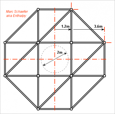
I want a railway to guide the shell that carries the experiment floating in vacuum... Here's a railway's truss that supports the vertical 150m railway and is hold at its bottom, to decouple it from the windshield tower. Though, I'm not quite sure that the railway and the bubble need decoupling from the windshield tower, especially if flights start only from ground level. The tower moves little in reasonable wind, <1m for 240km/h hence <0.1m for 80km/h and still improvable, and the experiment moves freely in the bubble. Fastening the railway to the windshield tower would gain stiffness and simplify the design. Anyway, here's a truss design that looks possible. It keeps 1m radius clearance with the windshield tower and hosts a D=2m bubble. This is a horizontal cut, the kind reader must imagine that some beams are inclined. Stress on the railway is hard to assess, so I've taken arbitrary beam cross-areas - warning - but at least these give pleasant resonant frequencies and are individually safe from buckling. The material considered is S355 steel; the truss resists 0.2g earthquakes, and AA7020 aluminium or a wider tower would improve that. The outer eight columns are OD=178mm t=5mm round tubes, the inner four W=140mm t=5mm square tubes. The horizontal and biased beams are OD=70mm t=4mm round tubes. The truss has 3m high stages and weighs around µ=560kg/m, totalling 84t. The truss' inertia is 0.17m4. The first flexural mode, holding only the base, corresponds to k*Z=1.88 so Z=150m injects the wave vector k=0.0125rad/m in the wave equation EI*k4=µ*w2 from which the truss resonates at 0.20Hz. At this lowest frequency, a flexural wave propagates at 101m/s, exceeding the bubble's maximum 50m/s, which I believe is important to keep the lateral position stable as the bubble falls down. The truss' shear compliance is, with only two inclined beams resisting in each direction, 35nm/N for each 3m stage or mean 12*10-9/N for the truss, so shear waves propagate at 380m/s and the first shear mode, holding only the base, is 0.65Hz. Torsional modes are faster. The 3m free column lengths can vibrate as half-waves with k=1.05rad/m. The 8*10-6m4 and 21kg/m square tubes resonate at 50Hz where they propagate a flexural wave at 300m/s. Marc Schaefer, aka Enthalpy
-
Found a Wiki article (about Liénard-Wiechert potential) that states that: "static fields (the first term) point exactly at the true instantaneous (non-retarded) position of the charged object if its velocity has not changed over the retarded time delay. This is true over any distance separating objects." http://en.wikipedia.org/wiki/Li%C3%A9nard%E2%80%93Wiechert_potential in the section "universal speed limit", written in normal language in the second to fourth paragraphs. An other article that states that, for a source of constant velocity, both the electric field and the gravitation field point to the present position: http://math.ucr.edu/home/baez/physics/Relativity/GR/grav_speed.html
-
Vacuum or low-pressure vessels are often needed, so the already described extruded profiles, the cast shell elements, the sandwich shell elements (possibly by diffusion bonding) have uses beyond hydrogen storage. Few examples: Some alloys are better cast under vacuum. Vapour condensers and the turbine that uses them. This one may prefer an Al-Mg alloy or titanium.
-

Challenge to received understanding of the Coeff of Static Friction
Enthalpy replied to Enthalpy's topic in Speculations
The table excerpt provided is wrong, by much. For instance, we take a coefficient of friction of about 0.17 for hard steel against hard steel in bolts, without any grease. -
Unfortunately, the model with plastically deformed contact points is too inaccurate to hold. It predicts a friction coefficient equal to the ratio of the shear flow stress to the compression flow stress, which is often near 0.6, and that's wrong even for most metals, whose friction coefficient is often between 0.12 and 0.4. These two numbers don't even vary in a correlated way. I know it's one historical model that is taught in books and courses, but there is no reason to believe it, use it, no teach it.


