-
Posts
3887 -
Joined
-
Last visited
-
Days Won
1
Everything posted by Enthalpy
-
Even if the expansion produced work, 7bar to 1bar would cool a diatomic gas (a perfect one, but the Joule-Thomson effect is small) to only 170K, not enough to liquefy oxygen nor nitrogen. The Joule-Thomson effect relies on gas imperfection, but typically the effect is smaller than the expansion of a perfect gas producing work.
-
I had put the body-centered cubic vanadium in the "brittle" box, but it's ductile http://www.webelements.com/vanadium/ http://en.wikipedia.org/wiki/Vanadium fine, this serves my purpose.
-
At Bremen, they pump to vacuum before each shot, and this takes 1.5 hour, limiting the repetiion rate. The pumps are already big: 32 000 m3/h. More frequent shots are a hot desire there. The drop tube sits anyway in a building, and a vacuum tank can stay unwatched as much as oxygen bottles are presently. The main tower consists only in part of a vacuum tube. You must add the wind shield tube, the experiment catcher and catapult, the instruments, and so on. Just by permitting the pumps to run with a proper pressure ratio (a single centrifugal stage gets possible) one saves on acquisition and electricity costs.
-
The contact potential is uniform across the junction, provided the temperature is even. But if you have a temperature gradient across one single junction, even without a hole at the center that would make a closed circuit patent to our eyes and understanding, then current will flow, yes. This current consumes heat at the hot junction and releases a part of the heat at the cold junction, so the current can provide an electrical power but at the cost of heat, and within Carnot's efficiency limit. Worse: Peltier and Seebeck elements have a bad efficiency, far from Carnot's limit. The standard thermal engines are way more efficient. Though, Seebeck's static operation can be considered advantageous, one example (is there a second one?) being Radioisotopic Thermal Generator (Wiki) on space probes far fro the Sun, which use red hot 238Pu and semiconductor Seebeck couples to provide electricity.
-
At the best terrestrial observation places and for proper wevelengths, our atmosphere is essentially transparent, and space observatories would improve little on that. Satellites are irreplaceable for: - Wavelengths that don't reach Earth's surface - Very constant transmission, say to detect exoplanets by the occultation of their star, or for star seismology - Observations periods of several days without interruption - Lack of atmospheric turbulence, improving the resolution. The atmospheric turbulence was a fundamental limit to the resolution before adaptive optics was available, that is, as Hubble was being developed. When Hubble was launched, adaptive optics began to compete with satellites, especially because ground telescope are bigger so they offer a better luminosity. Presently (James Webb) a space telescope must be huge to bring a resolution advantage.
-

Gravitational Interferometer and Kalman
Enthalpy replied to Enthalpy's topic in Astronomy and Cosmology
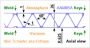
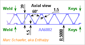
The D=1.25m vacuum tube of Ligo is made of 3mm 304L stainless steel with stiffeners http://core.kmi.open.ac.uk/download/pdf/4870869.pdf and perhaps maybe 4mm of aluminium extrusion are cheaper. Whether the longer weld seams are affordable is unclear. Also, the steel was baked at 444°C to desorb hydrogen, but aluminium should become permeable earlier. At least, the following tailor-made section shall resist the outer pressure - with margins, so the diameter can increase. Marc Schaefer, aka Enthalpy -
These are two different constructions with similar names. Two metals can pade a contact potential, they can also expand differently - and the uses differ. Yes, a contact between two metals makes a potential difference. At a uniform temperature, this can't be observed with a voltmeter because the circuit closed around one contact contains one or several contacts more that go back to the original metal or material, and the net sum is zero. Though, other methods can observe this potential, for instance an electron beam. This is difficult because electron work functions depend a lot on the surface condition. Semiconductors have also a work function, a contact potential and so on. Their Peltier and Seebeck elements are better than metals because the Fermi level varies more than with metals.
-

Gravitational Interferometer and Kalman
Enthalpy replied to Enthalpy's topic in Astronomy and Cosmology
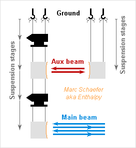
The Kálmán filter doesn't need a second tube - good, since the tubes make much of the observatory's cost. Movements assessed at each end of the tubes can feed the filter. I propose here to keep the observation of noise by light and deep at the suspension chain, as this is cleaner than an accelerometer at low frequencies, better oriented, and already well filtered. The observation of noise needs that both ends of the auxiliary path respond differently to ground movements; the filter can live with a deformed, indirect observation. The sketch shows one and approximately two stages of low-pass, so even at frequencies of equal amplitude attenuation, the phase differs (here nearly 90° versus 180°). In real life, the noise would be observed deeper in the suspension chain: not as deep as the main beam, and with chains of different reactions to ground movements, for instance different numbers of stages. ----- Common to all versions: feed the identification part of the Kálmán filter only when the ground moves enough to perturbate the useful signal, so that the filter sees a true transfer. The rest of the time, use the freezed identified transfer function; the suspension chain won't change its behaviour quickly anyway. Marc Schaefer, aka Enthalpy -
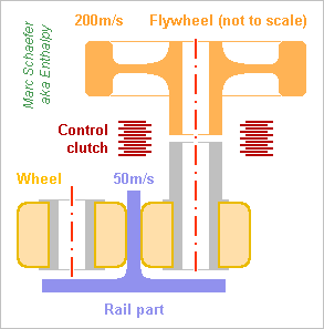
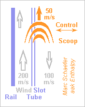
Here are drawings for the drag compensation engines. I'd have the two flywheels for up and down trip at different locations on the shuttle. A gear can power also the second propulsion wheel. Permanent force against the part of the rail gives grip. The motor that accelerates the flywheels prior to the trip can be on board, the energy source not necessarily. This is the liquid version; for a gas, imagine a De Laval turbine. The used liquid lows to a container. The pump to the bladder accumulator can be outside the shuttle. Yes, a jet of liquid exiting the shuttle could have propelled it without a turbine nor motor wheel. Yuk! The rail is at left and the shuttle at right on this sketch. The shuttle plunges its scoop more or less deep in the wider tube through the slot to control the propulsive force. More sketches should follow for this scoop engine. Marc Schaefer, aka Enthalpy
-
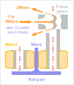
One more drag compensation engine: A turbine can rotate a wheel, directly on one shaft. Energy comes from pressure gas in a tank travelling with the bubble's shell. About 1kg air at 12bar (0.4m sphere) can pass through a small De Laval turbine. Air expands to 1bar 150K 550m/s, the turbine mean blade diameter is twice the wheel diameter hence runs at 100m/s, air exits at 350m/s which exploits ideally 59% of its enthalpy. For 300N and 50m/s at the wheel, 0.17kg/s suffice. Alternately, nitrogen at 350bar (210 bar for servovalves) can push a liquid (hydraulic oil) out of a bladder. A nozzle to 1bar makes a 300m/s jet. The Pelton turbine has the wheel's diameter, so for 300N and 50m/s at the wheel, the liquid exits the turbine at 200m/s, exploiting ideally 56%, and 0.6kg/s liquid suffice, again <1kg for the complete trip. The hydraulic option is more compact and I expect less leakage worries. Have one engine per direction. Drawing, yes... Marc Schaefer, aka Enthalpy
-
It's not only a belief, it's observation. Graphite doesn't burn. One more example are brakes for race cars, which were made of carbon before SiC. Use put them orange or yellow hot in air but they didn't catch fire, with or without speed afterwards. In addition to ovens that use graphite as refractory bricks. "Burn" can mean several things. If you have already a source of heat, and preferably in oxygen instead of air, then graphite will combine slowly with the oxygen and disappear - a bit faster than in hydrogen for instance. This is not the same thing as burning without aid, in air at normal temperature, which normal people call "burn". For instance soot from an acetylene burner is essentially graphite, and despite being really hot, in tiny chips, and having oxygen available as soon as it mixes with air, it doesn't burn and stays as soot. From the clear and ubiquitous evidence, I won't change my mind. ----- Graphite is produced from carbon-rich substances like tar or coke after many hours or days at a very high temperature. Manufacturers make this effort because coke is not graphite. Coke still needs to release volatiles and to rearrange.
-
Hi, The worry with galactic rotation is in the speed profile. The speed of globular clusters should decrease with their distance to the galaxy's center but it doesn't, telling that there is much mass in a galaxy which is not at its center and which we don't see. The recession speed, acting equally on all globular clusters or a remote galaxy, doesn't change that. By the way, we also observe the abnormal rotation profile for our own galaxy.
-
The black holes are observed. At our galaxy's center, we see within one human life stars move and accelerate at a pace that tells a mass is there, so heavy and so compact and so black that it is a black hole. Buy a newer book maybe?
-
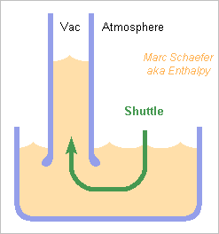
----- Catapult ----- The drop tube at Bremen can catapult the shuttle upwards from the tube's bottom in order to double the microgravity time. A pneumatic jack of direct action is uncomfortable, for instance 10m stroke and 0.25m diameter. Building it lighter than the shuttle, and braking it smoothly enough at the stroke's end, must have been a challenge. Bungees are a viable alternative. I used some to propel 60kg at 120km/h (and a kg much faster by accident) and the extrapolation to 300kg and 180km/h is reasonable - I didn't claim: "very small". Mines were half a dozen pairs (or better, U shapes), as thick as a thumb, ~60m long stretched, possibly 20m loose, and gave their energy in the last 10m essentially. Extrapolation here would need some 70 pairs if keeping this diameter. For the microgravity catapult, I'd stop them with ropes, still stretched after 10m stroke. They can run in smooth metal rings for all their length but the last 10m to keep them out of the way and help stop them. The ropes can pull them to the side, out of the falling shuttle's way. Bungees are non-linear, non-reproducible, and vary a bit over time. The use must adapt to individual characteristics given by the manufacturer. I'd provide anchor points moved by chains or screws, adjusted individually for each bungee pair. The actuator that stretches the last 10m then measures the force over the way to determine the precise starting point. Using the bungees to brake the fall is tempting, provided something prevents the rebound. Drawings should follow. Marc Schaefer, aka Enthalpy ----- Free floating ----- Instead of evacuating the whole drop tube, we could transport a vacuum bubble around the falling experiment without touching it. Aircraft in parabolic flight achieve a better microgravity by releasing the experiments and let them float in the cabin's air. Floating in vacuum would improve. Air drags the bubble's shell a lot. Even a 300kg unaided shell with Cx=0.17 would move by 2-3m during the way up relative to the free floating experiment inside, so this is an option for a much heavier drop tube rather. At present sizes and masses, it's better to compensate all drags - but thanks to free floating, this doesn't need much accuracy: the bubble's shell can move around the experiment if it doesn't touch it. I wouldn't let the bubble shell move unguided in the tube. Among others, I know no safe means that keeps the aerodynamical stability in two directions. But for crash tests, polyurethane wheels in rails guide a test car to 120km/h, so 180km/h must just be tried. After all, their manufacturer refuses to give any information over 5km/h anyway . The rail must be reasonably straight and smooth. For parabolic flights, the pilot steers the aircraft around a free floating item to keep it centered in the cabin. Though, I feel this too difficult for a machine and would rather have accelerometers at the bubble shell and control its speed and position to zero g. Drawings should follow. Marc Schaefer, aka Enthalpy ----- Drag compensating engine ----- It must work at +50 to 0 to -50m/s, provide an estimated +300 to -300N, but survive the initial 20g and 120kN if it doesn't provide them: this combination is challenging. A steel cable does it for crash tests, up to 120km/h, with enough position accuracy. The cable can stop within some 10m (compare with the catapult) and is about as heavy as the car; it takes big wheels, a strong pre-tension, strong brakes and so on. This would provide noth the initial speed and the free float control. While maybe feasible, I don't prefer this solution: it worked after a long development, doesn't fit the 10m acceleration naturally, and is oversized for the free float phase. Rocket engines expelling lukewarm nitrogen, carbon dioxide... are more or less possible. They need much propellant, like 50kg, plus the containers. Not convenient. A linear electric motor would work. I'm not quite sure all experiments accept its magnetic leaks. ---------- The bubble's shell has wheels at a guiding rail. These can propel the shell. Mean 50% of 300N over 150m need 23kJ, which one 10kg 200m/s flywheel per direction can provide through well-controlled clutches: electromagnetic, hydraulic, possibly adapted to a gas. The wheels need enough pre-compression to have 150m/s at the catapult's exit. Hard teethed wheels might be an option though unpreferred. ---------- The rail that guides the bubble's shell can have slotted tubes. The bubble's shell plunges to a controlled depth one of two anchors that deviate air moved at 200m/s in the slotted tubes by fans immobile in the tower. Air can climb in one tube and fall in an other, with the anchors scooping some from one to deviate it by 180° and possibly inject it in the other, similar to a Pelton turbine. Deviating 1kg/s with 0.5dm2 scoop section would suffice. The air can have a smaller side speed in the slotted tubes in addition to the vertical speed. This side speed may or not be a swirl movement within the tube. The side speed helps to keep the flow in the slotted tube if the tube's lips have slightly different heights; it also helps to inject the quick air in the tube and evacuate it. I expect several fans must spread along the track; possibly they rotate just over 200m/s and let the air turn by 180°, taking it from one slotted tube and injecting it in the other - many arrangements exist. A similar Pelton blade could deviate a liquid jet instead as the catapult, but how dirty. Drawings should follow. Marc Schaefer, aka Enthalpy
-
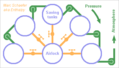
----- Put the shuttle in vacuum ----- At least in Bremen, the whole vacuum tube is evacuated from 1atm to 10Pa before each experiment. This takes much power and time. A first alternative would keep the tube void and introduce and remove the shuttle through a siphon: For instance vegetable oil has a good vapour pressure. While economic, quick and reliable, this method wastes height and is dirty. ---------- The other alternative is of course an airlock. Maybe with doors that slide to the side and are pressed upwards by a separate hydraulic or electric actuator; a hydraulically inflated seal ring is natural in this context. I described an airlock with saving tanks, as inspired by water saving basins http://www.scienceforums.net/topic/78116-airlock-with-saving-tanks/ and here's a sketch for the drop tube: The saving tanks are evacuated in advance to a logarithmic scale of pressures. To evacuate the airlock, it's allowed to discharge in the saving tanks of decreasing pressure. This saves time and peak pump power. One mode of operation that saves energy takes air from the still not re-evacuated tanks when the airlock is refilled. This evacuates some tanks for free, but not all: for a given pressure step in the airlock, the tank that refills it has a pressure 2-3 positions higher than the tanks that evacuates it. Here from 100kPa to 10Pa it still looks interesting. From 100kPa to 5Pa with 9 tanks (only 5 sketched), dividing the airlock pressure by 3[super]9[/super], the relative pressure could be at each step: Begin with 3.0*P in the airlock and 0.6*P in the 5 times bigger tank, end with 1.0*P in both. The total volume of the tanks equals 45 times the airlock, not little. Since the discharge process is isothermal only in books, air should be circulated between the airlock and a tank once the pressure is even, both to evacuate and refill the airlock. Limited temperature swing is an advantage of the saving tanks. Marc Schaefer, aka Enthalpy
-
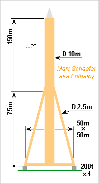
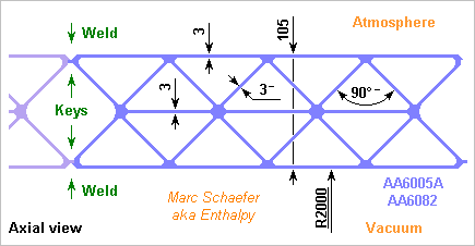
----- Windshield tower ----- The decoupled tower that surrounds the vacuum tube has, in Bremen, about 10m diameter of concrete, which must weigh many 1000t and need long construction work at height. A first alternative would use a decommissioned mine shaft, the mine itself, or caves. An other alternative makes the tower of aluminium extrusion (or of a covered truss): much lighter, possibly cheaper, assembled horizontally. Among many, the following design needs 115t of aluminium and 830t of ballast which can be a part of a surrounding building, to break at twice the force of 240km/h wind: The windshield tube and the 2.5m diameter legs have their wall of the same extruded profile: Marc Schaefer, aka Enthalpy Thanks for your interest! I find puzzling that people build 150m tall towers to get few seconds of microgravity - the experiment must be designed around this constraint. I also imagine that many experiments measure subtle and faint effects but decelerate from 160km/s within very few meters. I like also the two 150m tubes in an other, hold only by their basis.
-
Both hydrogen and carbon burn in coal, but carbon alone doesn't sustain a flame. Coke is pyrolyzed coal (or petrol) but it's not graphite. It's one possible input material to produce graphite parts or graphite matrices after a much longer and harder heat processing. Graphite doesn't sustain a flame. All my attempts with massive graphite parts consistently showed a lack of ignition, even with an acetylene burner and due patience. That's why it's used as a refractory coating in furnaces, including in air environment. I once brought graphite fibres orange to yellow hot when I accelerated the polymerization of an epoxy matrix on graphite fibres. The points of electric contact where I injected about 1kW in the locally nake fibres were bad as usual, these points sort of caught fire locally but extinguished themselves spontaneously as soon as the current had to seek a different path. This was despite fibres ease fires much. Graphite didn't burn at Windscale, according to Wiki http://en.wikipedia.org/wiki/Windscale_fire#Wigner_energy the damage to graphite was limited and localized around the fuel rods. But if you saw the graphite after the fire, tell us!
-
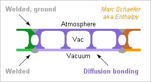
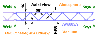
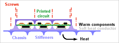
Hello everybody ! Some experiments (clocks, atom interferometers, tests of satellite parts...) must run under zero gravity. Among the methods: Space station - Back seat on a satellite - (Small) own satellite Seat on a launcher's side booster - own sounding rocket Parabolic flight aeroplane Drop tube. A drop tube provides among the best microgravity quality if not the longest. It's up to 150m tall, evacuated to eliminate the air drag, and the experiment drops through it for 5s, or 10s if it's thrown upwards from the base http://en.wikipedia.org/wiki/Drop_tube http://de.wikipedia.org/wiki/Fallturm_Bremen that's unusual engineering and I hope you find it puzzling too. ----- Vacuum tube ----- Vacuum vessels are common, but not of this size... 110-140m long and I suppose 4m diameter. Wiki tells it's separated from the surrounding tower to decouple the wind force, and made of steel. Aluminium extrusions, assembled by welding, can make this tube as well http://en.wikipedia.org/wiki/Extrusion A tailored die costs few k€, the preferred alloys resist corrosion well and are easy to weld. Profiles are commonly 15m long. At 83t for 140m, it's lighter than steel and possibly cheaper. ----- Shuttle ----- It may host varied experiments, protect them from the brake hardware, keep the experiment in high vacuum outside the drop tube... Here are shuttle shells made by diffusion bonding followed by welding, similar to http://www.scienceforums.net/topic/73798-quick-electric-machines/#entry827449 It makes individual shell elements more expensive, but nice to assemble in a smooth three-dimensional shape. A cylindrical shuttle instead would suggest extrusions again, here an example weighing 59kg for D=0.8m L=2.4m: ----- Components cooling ----- Standard satellite integration must be helpful to cool electronic components in vacuum and hold the circuits when braking: On my satellite's transmitter, I soldered on the printed circuit a 1mm copper plate, photoetched the same way, to evacuate heat to the sides instead. Other methods include heat pipes within the boxes and at the chassis, for bigger power. Marc Schaefer, aka Enthalpy
-
Thanks for your interest! I have nothing against rules with exceptions, which is the common case in chemistry or metallurgy... Physics likes rules without exceptions, but this is possible in some domains only, and as it looks chemistry isn't such one. We could even formulate it the other way: the physicists are the people who chose a domain of expertise where rules apply neatly. What bothers me is that any link between the crystal organisation and ductility has as many exceptions as followers, from the list I checked above. This looks like one "rule" that perpetuates only as a habit that no-one checks. So much that we read false claims like "alpha titanium is fragile because hexagonal", "zinc breaks upon bending because hexagonal" or, more recently, "0.3% Sn and Pb make Mg alloys ductile by adding slipping planes". This idea seems hard-wired in the conception of metallurgy. Anyway, I don't even see why more slipping planes should make an alloy more ductile. Three planes should suffice.
-
Hi Hanir, welcome here! Home-made cars exists, from simple to elaborate. Definitely a matter of individual expertise. Some countries demand a homologation to allow a car on the streets. This can be simple or long and costly. Depending on local availability and use, an electric car may be easier to build at home than a petrol one.
-
Their reciprocator design looks interesting and may be the innovating part in the design. The designers were probably aware of the friction drawback and searched an answer. Could this be transferred to hydraulic pumps and engines? An other drawback I see for the rotating cylinders is the inertia. Much worse that if moving only pistons and a crankshaft. That must be a handicap on a race car, to be compounded with the advantages. On a standard petrol engine with reciprocating pistons and crankshaft, many small cylinders fill and empty more quickly, so they can improve this efficiency or run faster, which gives more power from the same volume and mass. That's why Formula 1 engines had V12 engines in the past, and aeroplanes far more. On big maritime engines it also keeps manageable part size. On consumer cars, the same parts make engines of varied power by changing the number of cylinders. Cams instead of a crankshaft: - Had they springs to pull the cylinders? Fine on hydraulic machines, serious drawback for combustion engines. At 6,000rpm one has to pull the pistons strongly. - Friction, sure. Which mean not only losses: it demands better cooling and reduces the parts' life.
-
Carbon and hydrogen. Coal, even anthracite, is a hydrocarbon. That's why one can light it, while insisting with the lighter under a chunk of graphite won't light it. Anthracite contains 92-98% carbon http://en.wikipedia.org/wiki/Anthracite which is as much as Pentacene C22H14, obviously called a hydrocarbon with its 95% C http://en.wikipedia.org/wiki/Pentacene
-
Efficiency of a class B amplifier: - On an existing one, measure the output power, the consumed power, compute the ratio. - On a design, evaluate the otuput voltage without distortion, the current consumed everywhere, compute. - In an abstract case, a class-B amplifier has a maximum efficiency, but real amplifiers don't come very near to this limit. See below. ---------- Note 1: less than the maximum output power reduces identically the current in the load and consumed from the supply, but because the voltage at the load diminishes while the supply voltage uses to be constant, this reduces the efficiency. So the best efficiency is at maximum power. Note 2: Power and efficiency relate to a sinusoidal waveform despite sounds are no sines; an other shape would give different figures. The absence of distortion on the sine gives one output power and efficiency. Accepting some distortion permits more output power and a better efficiency; manufacturers may give figures for this second case. Note 3: loudspeakers (and sonar transducers, and many more) have an extremely variable impedance which is mainly reactive. To be comparable, the measures are made with the nominal output load, for instance 4 ohm or 8 ohm, perfectly resistive. Note 4: the power supply wastes power as well, so one should tell if the efficiency is from plug to load, from DC supply to load, or more bizarre. ---------- For the maximum efficiency, take a push-pull output supplied with +V and -V (an H bridge would have the same efficiency) that drives a purely resistive load R. The output components (usually transistors) give at each instant of the waveform the proper voltage to the load and drop the rest - this is what class D would improve. The corresponding load current is drawn from the supply at each instant. The (conventionally sine) output waveform gets V as a peak, so the rms load voltage is V/sqrt(2) and the rms load power is 0.5*V2/R. The (sine) load current comes from the power supply, it's V/R at the sine's peak. Because the DC supply delivers current at a constant voltage, the drawn power depends on the mean current, which is 2/pi * V/R, and the drawn power is 2/pi * V2/R. The +V rail gives this power for one half-wave, the -V rail for the other half-wave, so over the complete wave, the drawn power is (2/pi) * (V2/R) as well. The maximum efficiency of the class-B amplifier is the ratio between both, or 0.5/(2/pi) ~ 78%. A real amplifier drops voltage in the output transistors even at peak output voltage and consumes current elsewhere, so figures like 60% would be very decent - for the undistorted sine wave in a resistive load, and so on. The power supply would also waste a lot; it was generally not regulated to improve this, and presently is rather a switched-mode one to save transformer size.
-
Interactions as well demand point electrons, be it between atomic orbitals, in a collision... Changed my mind. In a model where the electrons would be diffuse, with a charge and mass density both multiplied by |Ψ|2, the electrostatic interaction energy around a pair of possible positions would be multiplied by |Ψ1|2*|Ψ2|2 but the mass only by |Ψ1|2 or |Ψ2|2, which would lead to a different hence wrong solution. So diffuse electrons are no alternative to the standard formulation: electrons spread according to Ψ, but around each possible position we shall compute with the complete charge and mass there. This is not patent for electrons that emit or absorb visible light in atoms, I guess because such photons have a wavelength much larger than the orbitals, so that only the electron behaviour averaged over the orbital influences the emission or absorption. ---------- The argument above does not apply as is to photons. ---------- Thanks to Swansont for the papers about Landé factor versus the size of a hypothetic composite electron. It puts strong limits on the distance between the hypothetic constituents of an electron.
-
Meanwhile I've heard comments of disbelief, especially about magnesium and zinc. I may have written too quickly about magnesium. The small ingot I had from then Péchiney (they told me "pure" with no more details) could be hammered thin (say 50% thickness reduction) without splitting. Though, most alloys guarantee only 2-5% elongation at break. In their 2009 paper "A Highly Ductile Magnesium Alloy System", W Gao and H Liu from Auckland university report 18-22% elongation at break for magnesium alloyed with 0.3-3% of Sn and Pb, optionally Al, Zr, Zn. That would be a welcome improvement. The paper doesn't describe the crystal structure, but at 0.3% Sn plus 0.5% Pb it's probably hexagonal like pure Mg. The zinc I took from batteries as a kid could be folded at 180° several times before breaking. At that time it contained 0.1% Hg or Pb. Sheets to cover roofs contain 0.1% Ti and can also be sharply bent at normal temperature. Some sources claim that this 0.1% makes zinc bendable; that would be an other case where alloying elements increase the ductility. Could ductility through alloying be a key to beryllium use? Up to now, people try to control the tiny oxygen proportion, but maybe some element addition is the way instead. One that scavenges the oxygen traces?


