Everything posted by studiot
-
 Setting aside the building of the pyramids for the moment. Do you honestly believe that the Ancient Egyptians had no ramps whatsover anywhere at all?
 -
We can, however agree that, as you said, translation is very difficult because it has to be not only from their language to ours, but their culture to ours. For my part I would have caught on much more quickly if the translation had been vessel instead of boat. We clearly have a greater range of words available and it is the skill of the translator to get the meaning across by selecting the appropriate modern word or phrase rather than disgorging the dictionary. Translating poetry is even more difficult.
-
Well we will have to agree to differ on this aspect, since I believe in calling a spade a spade.
-
The Ancient Egyptians has wells. What did they use to haul water out in? And where in the English Language has anyone ever written that they hauled water out of a well in a boat?
-
I'm gald you have managed to convince yourself, since some of your arguments have a plausibility. But, and I don't care who does the translating, a boat is not and never has been a container of water. Unfortunately such a basic blunder can only cast a shadow over other statements of translation. But if you are going to achieve any credence with the modern engineering community, you need to speak to them in a language they will understand, and further not try to tell them that it is easy to move multi-tonne objects hundreds or even thousands of metres basically horizontally but generally uphill.
-
The story of Smeaton's Tower is fascinating in its own right, but its relevance here is that, like the pyramids and masonry arch bridges, it is a gravity compression structure. The Tower was built as a lighthouse on a rock in the English Channel. Smeaton's Tower replaced a couple of previous structures that had not withstood the rigours of the marine environment. It was a masonry structure where all the blocks had to be meticulously fitted together to provide the strength against the battering waves, using their combined weight. It was conceived as being 'grafted onto the native rock' and every block was cut to fit the shape of the supporting natural rock. Because it was built so well it did withstand the conditions, until it was dismantled and rebuilt as a tourist attraction in Plymouth. You ask why the builders of the pyramids needed to level the site and construct a strong and stable support platform for the pyramid. Well perhaps they found this easier than Smeaton's solution of cutting blocks to fit the local topography. Whichever the pyramids obviously have a sound and stable foundation, or they would not have stood so long. Gravity compression structures do not take kindly to differential movements of the foundations. But then, perhaps they killed two birds with one stone (forgive the pun) and created a water catchment basin as well. Every block in the pyramids was transported many many times as far horizontally as vertically. This was no mean undertaking and I did not realise you were discounting this part of the journey. Yes the builders may have had lifting apparatus that lifted the blocks vertically. But I doubt they had apparatus that could lift and translate the blocks as well. It would also have been a lot easier if you had translated whatever word it was to bucket not boat since you are suggesting that the lifiting was performed via counterweight, filled with water. To a modern engineer the term hydraulic lifting implies the use of water pressure not its weight. Finally you ask (apparently rhetorically) why would someone clear a site and then leave it? Well I can point so several such instances within a mile or two here, where sites have been cleared and left for some years. The intention is obviously to one day develop these sites. So all you are describing is readily understood in practical constructiuon terms. But that does not mean you do not have a point. It just shows that ancient and modern builders were not as far apart as is sometimes thought. Which rather strengthens my observation that termporary works are generally removed at the end of construction so you will never be able to deduce what was used from what remains.
-
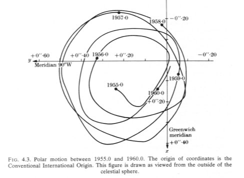
Ok I get the picture you are not interested in anything anyone else has to say. Yes your conclusion is possible. But there are others, and as someone who has considerably more construction experience I offered you the story of Smeaton's Tower. It contains the Civil Engineering theory for alternative reasons, which I would think are linked to the reason the pyramids have stood for so long. Did you look it out? Again there are potential alternative explanations. I don't doubt some of the observable detail in what you say but your statements are given to hyperbole and sometimes lead to into the realms of mumbo jumbo that 'pyramidology' is so famous for. Do you have any idea of the true implications if your statement 'perfectly aligned N/S' ? The ancient Egyptians knew nothing of magnetic compasses and the magnetic poles. But they had clear night skies and mapped some stars, including Polaris. Here is the variation of North over a 5 year period, due to the Earth's 'wobble' about its axis (source Bomford's Geodesy) How much do you think it has varied over a 5000 year period? So yes, but all means put forward ideas, but be prepared to test them against practical observations and other credible alternatives. We can then re-examine your claim that the artificial limestone 'pavement' was meant for water collection is the only credible explanation. That is the way to take a few more steps along the road to truth.
-
'Light blue touch paper and retire immediately' This is the problem, n'est pas? This whole tirade that pours out when someone mentions the word 'ramp'. If you will listen, I will relate the story given by Professor Harvey following his visit to China to study their bridge building program. It concerns the building of a (modern) bridge by the local Womens's Institute, entirely by manual labour (ie no modern mechanised plant). The bridge is a viaduct crossing the flood plain of one of China's major rivers and is several kilometers long.
-
In all honesty I think you have said a great deal more ( though you were not the only one). This thread could have been cut in half and half again and be much more scientifically useful as a result. I have already acknowledged that I am almost totally ignorant of the linguistic background here so cannot comment on that aspect. Is it more important to arrive at the truth (as equal to a thesis that fits all known facts) or to demolish some one else's ideas?
-
Strange, can you prove your alternatives and can you say that you are offering cladking a fair hearing? Cladking has contradicted himself many times in this thread, but he has also made many valid points that merit consideration and surely the truth is the nobody knows what actually happened and there remain many unanswered questions. If someone misapplies the quadratic equations formula we do not lay into him but try to get him to use the formula correctly to arrive at the appropriate answer. So it should be with more nebulous thoughts. Looking around at the other threads currently available I see a number of really crackpot subjects plus some that have nothing to do with science. Surely we all wish to promote subjects worthy of discussion?
-
For a self professed linguist you have taken remarkably little notice when I have explained that I use some terms in their technical sense. Limestone pavement is one of them. I have already posted a link to the geological definition. Several times in this thread I find that I see a post from yourown goodself and it is a response to someone else so I leave it. But later (by chance) I find additional response to one of my questions appended, after I have posted. Are you saying the aquifers are not limestone? Do you have any data on the strata to back up this claim about the depth of the features? There are some pretty substantial underground limestone features in other parts of the world.
-
Thank you for that useful answer. +1 I had a quick shufty round Google and found a lot of mumbo jumbo. However does that not make it typical Karst scenery? Every site on Earth can probably claim at least one unique selling point, but you offered the tantalising suggestion of numerous usp's. and a nearby large river that moves about in its course over centuries? there are quite of few of those around too. I'm not sure about the composition of the salts in the aquifer water, I would have to look further into those. But I would be very suprised if a substantial limestone pavement of a venerable age measured in thousands of years did not contain fissures and caves.
-
I would be interested in some information about this.
-
You have said a lot about language, but I have found what you mean by the above statement very difficult to divine, and I think that also applies to others. This, I fear, has lead to much confusion and unwarranted recrimination. We must keep working away at communication.
-
I hope you don't subscribe to this nonsense. Dragging stones off the ship is at least as bad as dragging them on. This is another question I asked earlier, but received no response to. Captain "Ere, guv, ye capsize my ship 'n all, an 'twill cost ee dear"
-
I wouldn't necessarily "expect" any sand at all to appear. That it does strongly suggests they either needed it for some function or that it was a byproduct of a natural process. It certainly seems that most functions that can be served by sand can be served by just about any sand so why would they haul sand from a far away desert to their own desert? This isn't to say that it mustta come up with the water merely that the gravimetric scan suggests this sand might extend all the way to the entrance as would be predicted by my theory. My theory is far more extensive than I usually let on especially among scientists. This is because it is derived from what Egyptologists believe is a book of magic. The ancient language could be highly expressive and many words were virtually sentences. Some concepts would have been almost impossible to express at all and even simple concepts could talke several sentences. By the same token some sentences could express a great deal of information and paint whole pictures. They aparently called G1 "the sandbank of horrible face bringing water" and this isn't even the ancient language but a confusion of it. There are numerous clues in the PT about what chemicals are in the 1% impurities; Copper sulfate, calcium carbonate, sodium hydroxide, sodium decahydrate, salt, sodium bicarbonate, copper hydroxide, siderite, "silicone" etc, etc... It should be a whole cocktail of chemicals that are implied or derived from what the builders actually said. I can't prove this because the tests won't get done. The reality is there but like "amun" it can't be seen. The Egyptians couldn't see it because it was hard to see, we can't see it because we refuse to look. Once again you are making things so difficult for yourself. I asked a simple question, seeking a simple answer. There was no trick question involved. Here is an earlier version of the same question. I am no expert on the subject of the pyramids, but have been involved in the building of many difficult structures myself and I can see that you have expended much effort researching this subject. It would, however, be nice if you would pay some attention to the lifetime of experience I am offerenig (for free) to perhaps further your subject. Several times we have arrived at a simple consensus where it is apparent that you and I are using technical terms differently. It would be helpful, to say the least, if we could do this more efficiently. Here is another practical and sensible question that could have been asked by the captain to the supply vessel crossing the Nile with the blocks. I've got yer blocks across the river guv, but the site is 5 miles inland. How do we get them there?
-
So why would you expect 'local' sand at this location? And why are you studiously ignoring my requests for hydraulic details of the boats which you allege carried the stones?
-
Perhaps we should clear up the term pavement? Do you mean an artificial flat area? Or do you mean the natural geographical presentation of the native country rock as here in limestone pavement https://www.google.co.uk/search?hl=en-GB&source=hp&q=limestone+pavement&gbv=2&oq=limestone+pavement&gs_l=heirloom-hp.1.0.0l10.1110.4250.0.7922.18.12.0.6.6.0.125.1252.5j7.12.0....0...1ac.1.34.heirloom-hp..0.18.1487.pRHiYbw_3I8
-
My confusion of geology stems partly from this quote I am confused because I am told that the pictures are of a limestone pavement. Limestone, so why is it suprising that they had to import sand if they need it? Sand does not come from limestone. And partly from these quotes Balsalt pavement in the same location as limestone pavement? Thank you for the comments about the water, as I understand it you are saying the quality of the Nile water was less attractive than artesian or spring water and that the collection basins were not for rainfall but to pond the subterranean water at its outlet. You still have not explained how the shallow draft boat you drew could displace enought water to float. Did you understand the question?
-
Desert Sand Basalt Limestone Your post # 63 picture. I'm having trouble reconciling these geologically speaking, but perhaps our geology specialist can explain? cladking, I have no idea of the human geography of the area at the time of the pharohs, but what do you think was the reason for building water catchment (rainfall?) basins in remote desert?
-
I really am confused now. Your sketch seems to me to indicate a (water lubricated?) ramp, where a sled is pulled up by suitable lines. I said earlier that there was no need for a slave army of men to pull the lines. I now understand your earlier reference to a funicular and a counterweight. There are many simpler ropage mechanisms they could have used, as in my earler references. One of these systems, including yours, could also have led to a vertical lift without a ramp, but it would have been necessary to bring (drag?) the blocks beneath the lifter somehow. Thank you.
-
And how did the sled-boat in your sketch displace enough water to float? Edit I am trying to take your ideas seriously so I wish you would stop disparaging egyptologists and ramps in your replies to me. I really don't know or care whether ramps or egyptologists were used. I have to discard more than half your posts as chaff to find some kernal to think about.
-
I'm sorry but I require considerably more convincing than your selective proclamations. That does not mean I support any other theory I treat them all the same. Nor does the use of ramps require men to drag anything. What do you know about the mechanics of 'dragging'? You say both that it is impossible to use canals and that canals have been found. I have never been to the pyramids so I do not know the site. You keep referring to cliffs, but I see no cliffs in any photos. You have (I think) told me that most of the stone is limestone quarried from within a few hundred yards of the pyramids. I was thinking the stone had travelled further. You state that derricks were not used, so how did they load and unload their ships? In particular how did they put large blocks of stone on board? If you try to drag a large weight aboard, all you will achieve is capsizing the boat or pushing it away. I am still waiting for the details of the boats capable of transporting 20 ton blocks.
-
It would seem that we cross posted as you added to your post whilst I was responding to your first line. Pressing the post button is easy to do, I have done it too early myself. So I am sorry if my last post came over as a tad strident. However you have still not responded to my main points. Hard information such as the distance from the pyramids to the quarry would really enhance discussion. Can you also list the height of the lift (ie to the top of the pyramid) and the rock material the blocks are composed of? Is there any evidence as to whether the blocks were cut/split and dressed on site or at the quarry? It would make sense to transport the stone by canal to site, but the canal would be at a fixed elevation, it would not run uphill as the work progressed. As I understand the history of engineering, the Ancient Egyptians were quite capable of using a loading/lifting derrick of the type in my logging link These could also have been deployed on the developing structure. A further possibility is that a very large ramp (as in Masada), larger than a pyramid, could have been constructed and the blocks lowered down to place. If you really want to explore the posiibilities, now is your chance.
-
The fact that the pyramids themselves exist suggest that some sort of temporary devices were used to build them. How about addressing my main questions? and please add this one What would be the draft of the boat (you keep using that term in preference to raft why is that?) that can reliably handle up to 40 tons displacement?