Lazarus
-
Posts
366 -
Joined
-
Last visited
Content Type
Profiles
Forums
Events
Everything posted by Lazarus
-
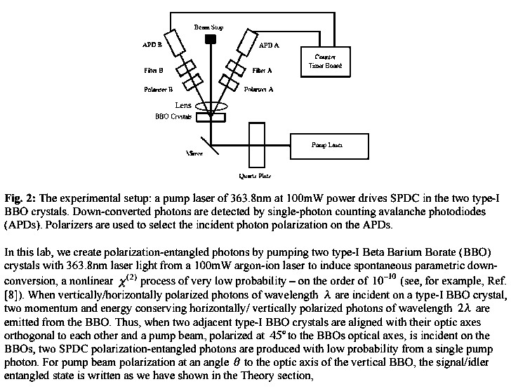
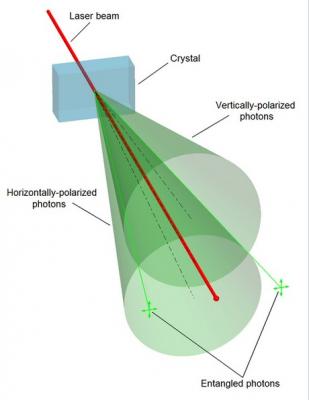
The 25ns is the window that is to catch both photons from one BBO, not to catch photons from both BBO’s in one window. The experiment is designed to space out the down conversions so that they happen one at a time. There is no requirement or expectation that both BBO’s will generate pairs at the same time. The output of a BBO is 2 polarized beams. All the photons in one beam have the same angle of polarization. The BBO’s are 90 degrees apart. When the left BBO is set so the left beam is vertically polarized and the right beam horizontal the vertical photons will always hit the left detector and the horizontal photons will always hit the right detector when both detectors are activated. The right BBO has the reverse effect.
-
The rate of generation of pairs is intentionally slowed so that there is normally one generation in the 25ns window. Whether the double generations are rare or not shouldn’t be an issue because they should not be counted. The detectors know which BBO the photon came from because the polarization is different when it comes from A than it is when it comes from B and the detector can tell us.
-
Here is typical time line so you can point out the error. A couple billion polarizer photons hit each BBO. One of the photon that hit the A BBO split into a pair of entangled photons which are recorded by the detectors. None of the photons that hit the B BBO split. Another couple billion photons hit each BBO some nanoseconds later. Same thing happens again, one A BBO photons splits and none of the B one do. A third set of a couple billion photons hit each BBO. None of the A photons split but one of the photons that hit the B BBO splits into a pair of entangled photons which are recorded by the detectors. The fourth time that a couple billion photons hit each BBO something rare happens. Both BBO’s have a photon split into two entangled photons. All 4 photons hit the detectors within 25 ns. What happens is dependent on the design of the Coincidence Monitor. It should ignore them because that is not in the playbook. None of the next batch of photons split in either BBO so no detections. Where is any indeterminacy involved?
-
You seem to be talking about the time difference in the 2 beams from one BBO. The time separation of concern is the time between the output one BBO and the other. The time increment that is allowed for one event is about 25ns. The coincident detections have to come from one of the 2 BBO’s. The BBO’s take turns. They very rarely both react in the same 25ns.
-
It is highly improbable that the mathematics is flawed. I appreciate your patience.
-
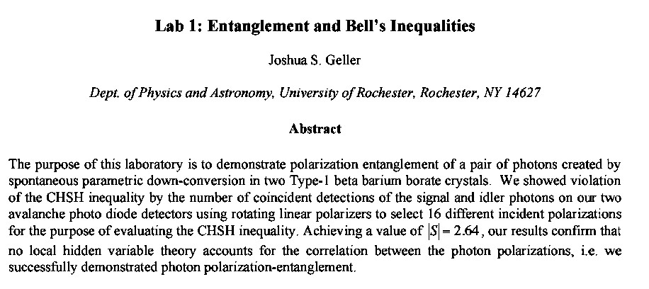
You are correct. It just wasn't refuted. Thank you for pointing out that there are 2 BBO’s in the source. I completely missed that. However, the problem is still there. The 45 degrees you mentioned does not cause the generated photons to be polarized randomly. The polarization is changed but each generated beam always has the same angle of polarization. There is a time separation between the generation of pairs between the 2 BBO’s so they are completely independent from each other. That means every thing about each incident can be calculated. There is no room for indeterminacy. The reason I didn't post the link to Geller's PDF is that the link is so long I had a problem with it. Searching for "entanglement bell joshua geller" will lead you to it.
-
The math is wonderful but does not necessarily match the real world. The physical experiment must stand on its own feet. We have already shown that the three coins in the fountain proof is not valid. It simply says that adding a non-negative number to a positive number can not make the positive number smaller. Geller’s description of the experiment requires that A beam particles reach the B detector. That should never happen.
-
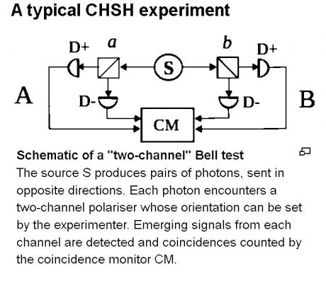
One of the better descriptions of a CHSH experiment is by Joshua Geller. You can download the full PDF description from the University of Rochester. In any CHSH experiment the SOURCE produces 2 polarized beams. The polarization in each beam always stays the same and should always go to the same detector. It does not make sense for the A beam to be going to the B detector.

-
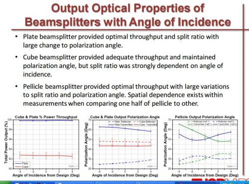
1 A beam splitter produces 2 polarized beams. Here is a table showing the polarizations which are dependent on the angle of the input beam. 2 The only thing indeterminate is which detector the photons will hit. The pairs of photons have a known polarization and a definite spatial relation. The “proof” is that we can’t know which proton goes to which detector. By selecting only cases where both detectors are activated we are only counting cases where each detector is always getting the same photon polarization.
-
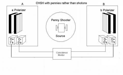
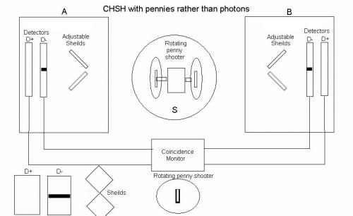
While writing a CHSH type device simulator with pennies rather than photons is became apparent that there were inconsistencies in the CHSH experiments. Perhaps the biggest error is in the justification of the photons being indeterminate. From the overlapping cones of the paths of the photons it is clear that both the vertically polarized and horizontally polarized photons can reach either polarizer. But since we only see cases where there is detection in both the A and B sides, the left polarizer only sees vertically polarized photons and the right polarizer only sees horizontally polarized photons. When a left photon hits the left polarizer the right photon hits the right polarizer but when a right photon hits the left polarizer the left photon can not hit the right polarizer. The left photon is to the left of the left polarizer so is nowhere close to the right polarizer. No indeterminacy.
-
Even with the objections, if a physical device can be built using CHSH experiment rules, that violates Bell’s Inequality, there is a problem that needs to be addressed. Here is an “impossible” classical, mechanical device, using pennies rather than photons, emulates the CHSH devices and gets similar results. Consequently, it violates Bell’s Inequality. The polarizers are grates with iron bars between the slits. The slits are the diameter of a penny wide. The polarizers are manually rotated to the desired settings, 0 – 22,5, 0 – 67.5, 45 – 22.5, 45 – 67.5. Pennies are fired at the polarizers in entangled pairs with state being parallel or perpendicular. The calibration sets the A penny parallel to the A slits. Pennies that pass through the polarizer fall into the D+ bucket and are counter as 1’s. The pennies that bounce off of the bars fall into the D- bucket and are counted as 0’s. A penny will bounce off of a bar and fall into the D- bucket and be counted as a 0 when the center of the penny comes closer to the bar than the radius of a penny times the square of the sine of the angle between the polarization of the penny and the direction of the bar. Here are some of the results of a simulation. Each run makes 10,000 trials with the coins hitting the polarizer at random points. adeg bdeg n11 n00 n10 n01 E 0.0000 22.5000 8534.0000 0.0000 1466.0000 0.0000 0.7068 0.0000 67.5000 1481.0000 0.0000 8519.0000 0.0000 -0.7038 45.0000 22.5000 8525.0000 0.0000 1475.0000 0.0000 0.7050 45.0000 67.5000 8563.0000 0.0000 1437.0000 0.0000 0.7126 S = 2.8282 adeg bdeg n11 n00 n10 n01 E 0.0000 22.5000 8530.0000 0.0000 1470.0000 0.0000 0.7060 0.0000 67.5000 1421.0000 0.0000 8579.0000 0.0000 -0.7158 45.0000 22.5000 8531.0000 0.0000 1469.0000 0.0000 0.7062 45.0000 67.5000 8573.0000 0.0000 1427.0000 0.0000 0.7146 S = 2.8426 adeg bdeg n11 n00 n10 n01 E 0.0000 22.5000 8519.0000 0.0000 1481.0000 0.0000 0.7038 0.0000 67.5000 1526.0000 0.0000 8474.0000 0.0000 -0.6948 45.0000 22.5000 8528.0000 0.0000 1472.0000 0.0000 0.7056 45.0000 67.5000 8539.0000 0.0000 1461.0000 0.0000 0.7078 S = 2.812 adeg bdeg n11 n00 n10 n01 E 0.0000 22.5000 8560.0000 0.0000 1440.0000 0.0000 0.7120 0.0000 67.5000 1461.0000 0.0000 8539.0000 0.0000 -0.7078 45.0000 22.5000 8566.0000 0.0000 1434.0000 0.0000 0.7132 45.0000 67.5000 8542.0000 0.0000 1458.0000 0.0000 0.7084 S = 2.8414 Here is the explanation of the range of the bounce being the radius of the penny times the square of sine of the angle between the coin and a bar. The overlap of the bar from pennies with their center close to a bar is the radius of the penny times the sine of the angle. Not all of the pennies that hit a bar bounce. Some of them just clip a bar. Depending on their alignment some will experience torque and not much force to make them bounce. That is compensated for by using the square of the sine rather than just the sine. The state of the coins is set to parallel with these numbers. Setting the state to perpendicular reverses the signs of the results. This device has the same functions as CHSH experiments, gets similar results and violates Bell’s Inequality.

-
That is the result of the calculation, the number of 1's = sin(angle+90) and also from the diagram. However that is moot because I agree with you that this device does not completely match the CHSH experiments. If I can find a device that better matches, i will present it for your inspection. Your help is appreciated.
-
At 5 degrees, the fraction of pennies that successfully pass through the hole and are counted as parallel is .9128 (91.28%). The fraction of pennies that hit the edge of the hole and are counted as perpendicular is .0872 (8.72%)
-
It is easy to change my mind. Just give me a clear logical reason and I change sides in an instant. Most of the mathematics of Quantum, Relativity and Astronomy is beyond question. The problem is in the contradictory, bizarre and sometimes just flat out wrong conclusions drawn from the math. For example: the D-Wave Quantum computer uses a Quantum DC SQUID as its Qubit. The DC SQUID is thought to be Quantum because the current flows in opposite directions at the same time in the loop with the Josephson Junctions. Mathematically, it is perfectly legitimate to describe the current as the sum or difference of 2 currents. Physically, that is not the case. All electrons are flowing in the same direction. The external magnetic field pushes some of the electron from one path to the other. Nothing Quantum there. The D-Wave computer is an updated analog computer. Your concerns are well justified. I am definitely out to destroy the ridiculous conclusions of current physics and replace them with logical, rational concepts.
-
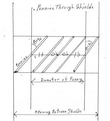
You are right. Not only are the cos^2(angle) and the cos(angle) not justified, they are not correct. The correct relationship is that the fraction of 1’s = sin(angle +90). Here is why. First, consider how photons passing through a polarizer work. Take the case where the wave length of the photons equals the width of the slits in the polarizer grid. When the electric component of the photons is aligned with the slits. almost none of the photons get through. When perpendicular to the slits, almost all get through. The magnetic field of the photons is aligned with the slits when the photons are getting through. For the pennies to match the photon’s magnetic field, 90 degrees must be added to the 22.5 and 67.5 degrees of the tests. To determine the relationship of the angle of rotation to the fraction of 1’s we can consider the coins whose centers are on one line perpendicular to the slits. Calculating the fraction of 1’s on the line (or half of the line) gives the fraction for all photons. This picture shows the shields, the edge of the hole and coins at significant positions on the line. The hole in the detector is equivalent to one slit of a polarizer. The hole’s width is = the diameter of a penny. The opening between the shields is set to equal the penny’s diameter times 1 + the sine of the test rotation. The shields would not be needed if we used multiple holes to match a polarizing grate. Coins that hit the edge of the hole are counted as 1’s. Coins that pass through the hole are counted as 0’s. 90 degrees is added to the test rotation to match the photon’s magnetic field orientation. The coins that will hit the edge of the hole are those whose center is within the sine of the test rotation angle plus 90 degrees times the size of the hole. (Size of the hole is the diameter of a penny) N = sin(angle+90) * d N is number of 1’s. d is diameter of penny. At 22.5 + 90 degrees, the fraction of 1’s is sin(112.5) = .9239. E = .8478 At 67.5 + 90 degrees, the fraction of 1’s is sin(157.5) = .3827. E = -.2346 S = .8478 -(-.2346) + .8478 + .8478 = 2.5434 S is closer to the CHSH test results around 2.4 than the Quantum prediction of 2.8.
-
The reason for cos^(angle) is that Malus' Law (I =Io*cos@(angle)) seemed similar. It doesn't matter because almost any reasonable choice will result in a violation of Bell's Inequality. For example: Using cos(angle) in place of cos^2(angle) produces A at 0 degrees and B at 22.5 degrees gives an E of .8478 A at 0 degrees and B at 67.5 degrees gives an E of -..2346 S = .8478 - (-2346) + .8478 + .8478 = .2.7789
-
As you pointed out, there were flaws in that model. This one should be more solid as it is closer to the CHSH experiments. It is difficult to find the actual data and the nitty gritty description of the CHSH devices but this has got to be pretty close. Again. thank you for your advice and patience.
-
OK. How about a classical device that violates Bell's Inequality. Here is an “impossible” classical, mechanical device, using pennies rather than photons, that emulates the CHSH devices and gets similar results. Also, it violates Bell’s Inequality. The source is a device that holds 2 pennies and fires them toward the shields. The 2 pennies are parallel, which is their entangled state. The drums holding the pennies rotate. When the drums are rotating the angle of the pins is undetermined. After the pins are fired they are determined but unknown. The pairs of shields can be individually, manually rotated to any angle. Most of the pennies are deflected by the shields. A few reach the first metal plate with a slit. Some pass through the slit and hit the second metal plate, D+. Some do not pass through, D-. When both the A and B shields are rotated by the same angle, the results do not change. When the shields are at the same angle, A and B get the same results, E = 1. When the shields are perpendicular, none of the results are the same, E = -1. In between the fraction of the pennies getting through is cos^2(omega), where omega is the angle between the shields and the slit. Since changing the rotation of both shields by the same angle doesn’t affect the results, only the angle between the A and B shields needs to be considered. The opening between shields is twice the width of a penny. The width of the slit is 99 % of the diameter of a penny. The fraction of pennies that get through is cos^2(omega). Omega is the angle of the shields, which is the angle between the shields and the slit. The slits are always at 0 degrees The only trials that are counted are those where both A and B detect something, D+ or D-. D+ will be considered a 1, D- will be considered a 0. There are 10,000 counted trials. The formulae we are dealing with are: E = (N11+N00-N10-N01) / (N11+N00+N10+N01) S = E(a,b) - E (a’,b) + E(a,b’) + E(a’,b’) E is the Correlation Coefficient. N is the number of detections of different combinations. a and b are angular settings of the polarizers. S is Bell’s Inequality For (a,b) the A shields set at 0 degrees and the B shields set at 22.5 degrees the number of A 1,0 counts is 10,000 times cos^2(0) = 10,000. The number of A 0,1 counts is 0. A01 = 10,000 – A10. The number B 1,0 counts is 10,000 times cos^2(22,5) = 8536. B 0,1 is 1464. B01=10,000 – 8536 = 1464. E = (A10+B10-A01-B01)*( A10+B10+A01+B01) E = (10,000 + 8536 – 0 – 1464)( 10,000 + 8536 + 0 + 1464) E = .7071 A deg B deg 1,1 0,0 1,0 0,1 Match E 0 22.5 8536 0 1464 0 8536 ,707 0 67.5 1464 0 8436 0 1464 -,707 45 22.5 Same as 0 22.5 .707 45 22.5 Same as 0 22.5 .707 S = .707 - (-.707) + .707 + .707 = 2.8
-
Nobody has objected to the conclusion that this interpretation on Bell’s Inequality is trivial. That implies that either Bell’s Inequality is trivial or this interpretation of Bell’s is flawed. Is there a better interpretation of Bell’s proof?
-
Let me add some more detail. Think of coins. A not B is the number of coins that are Gold, Tiny and either Bright or Dull (GTB+GTD). B not C is the number of coins that are Large, Dull and either Gold or Silver (GLD + SLD). A not C is the number of coins that are Gold, Dull and either Large or Tiny. (GDL + GDT) So GTB + GTD + GLD + SLD >= GLD + GDT That is GLD + GTD + anything non-negative >= GLD +GTD (GTD=GDT) From http://www.techlib.com/science/bells_inequality.htm
-
Bell's Inequality (in a simple, comprehensible form anyway) states that in a group of items that possess three properties, A, B, and C, the number of items that possess property A but not B plus the number of items that possess the property B but not C is greater or equal to the number of items that possess property A but not C. Assign A as Gold vs Silver, B as Large vs Tiny, C as Bright vs Dull. That leads to the trivial inequality, GTB+GTD+GLD+SLD>=GLD+GTD. Is this wrong?
-
What happens to space contraction with light in opposite direction
Lazarus replied to Lazarus's topic in Speculations
The confusion factor was the train explanation where the distance light travels is reduced by the contraction and the time remains the same. That doesn't seem to match the way Relativity handles it. Shrinking both distance and time will make it match. Please pardon the dumb question. -
What happens to space contraction with light in opposite direction
Lazarus replied to Lazarus's topic in Speculations
It would appear that the contracted distance would make the measurement of light speed come out greater than c. -
When an object is moving space contracts in the direction of travel so light traveling in the same direction shows a constant speed.. What happens to the space contraction when the light is traveling in the opposite direction from the object?
-
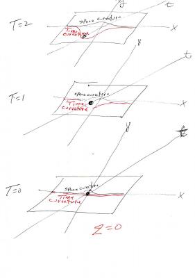
It could be that the reason for the change of direction of light involves the time portion of the space/time curvature. The bending of the line in space may actually match the diagram at time = zero. That would not change with time. If we consider the bending of time the result is not symmetrical Combining the space curvature with the time curvature could give a correct result because the time that it takes for the photon to pass the sun is enough for the time curvature to be modified .